


285
Learning Advanced Features
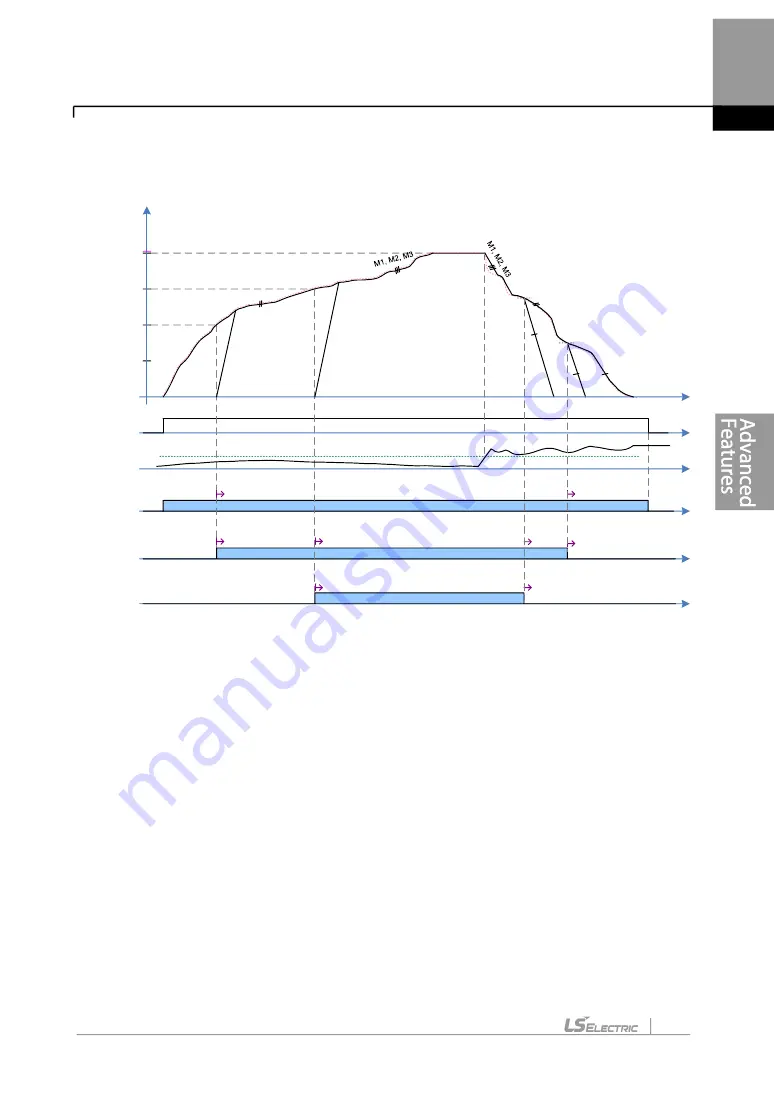
It is a mode to control motors turned on with the same PID output frequency.
The picture below shows that the priority is “Motor1 (M1)
Motor2 (M2)
Motor3 (M3)”.
(The priority can be changed automatically according to operating time).
St art Freq 1
St art Freq 3
Out Freq
High Freq
t
M1 OutFreq
M2 OutFreq
St op Freq 2
St art Freq 2
St op Freq 3
M3 OutFreq
Run Cmd
FeedBack
PI D Reference
M1 Cmd Freq
PID Ctrl
M2 Cmd Freq
M3 Cmd Freq
Main Motor
M1, M2
M3
M2
PID Ctrl
PID Ctrl
Main Motor
Main Motor
Main
Motor
Aux Motor
Main Motor
Aux Motor
Aux Motor
Aux Motor
Aux Motor
Aux Motor
PI D Output
PI D Limit High
M1
M1, M2
A condition that extra Aux Motor is turned on
.
After a real operating frequency reaches the frequency set in Start Freq belonging to the
next priority number and the time set in AP1-53(Aux Start DT) passes, AP1-44(Aux Motor
Run) increases (+1). In addition, Aux Motor with the next priority of Main Motor is turned on
and the new operating Aux Motor becomes Main Motor. Operating motors can be controlled
together by PID. It is possible to check the priority in [AP1-45/46 Aux Priority].
A condition that Aux Motor is turned off.
If the real operating frequency of Main Motor is lower than the frequency set in Stop Freq,
AP1-44(Aux Motor Run) decreases(-1) after the time set in AP1-54(Aux Stop DT) and the
present Main Motor becomes Aux Motor, decelerating based on time of [DRV-04 Dec Time]
until 0Hz.
At the same time, the rest of operating motors last PID control. It is possible to check the
priority in [AP1-45/46 Aux Priority].
5.44.8.3
Re-arrangement of priority based on operating time.
Summary of Contents for LSLV-H100 Series
Page 17: ...Preparing the Installation 4 37 90 kW 3 Phase ...
Page 18: ...Preparing the Installation 5 110 132 kW 3 Phase ...
Page 19: ...Preparing the Installation 6 160 185 kW 3 Phase ...
Page 20: ...Preparing the Installation 7 220 250 kW 3 Phase ...
Page 21: ...Preparing the Installation 8 315 400 kW 3 Phase ...
Page 22: ...Preparing the Installation 9 500 kW 3 Phase ...
Page 35: ...Installing the Inverter 22 ...
Page 50: ...37 Installing the Inverter Input and Output Control Terminal Block Wiring Diagram ...
Page 104: ...91 Learning Basic Features 0 10 V Input Voltage Setting Details V1 Quantizing ...
Page 181: ...168 Learning Advanced Features PID Command Block ...
Page 182: ...169 Learning Advanced Features ...
Page 183: ...170 Learning Advanced Features PID Feedback Block ...
Page 184: ...171 Learning Advanced Features PID Output Block ...
Page 185: ...172 Learning Advanced Features PID Output Mode Block ...
Page 198: ...185 Learning Advanced Features EPID1 Control block ...
Page 199: ...186 Learning Advanced Features EPID2 Control block ...
Page 220: ...207 Learning Advanced Features ...
Page 235: ...222 Learning Advanced Features The Time Chart for the Exception Day ...
Page 506: ...Table of Functions 493 ...
Page 520: ...Table of Functions 507 8 16 4 Cooling Tower MC4 Group ...
Page 549: ...Troubleshooting 536 ...
Page 569: ...Technical Specification 556 11 3 External Dimensions 0 75 30 kW 3 phase 37 90 kW 3 phase ...
Page 570: ...Technical Specification 557 110 185 kW 3 phase ...
Page 601: ...588 ...
Page 602: ...589 ...
Page 603: ...590 ...


