282
Learning Advanced Features
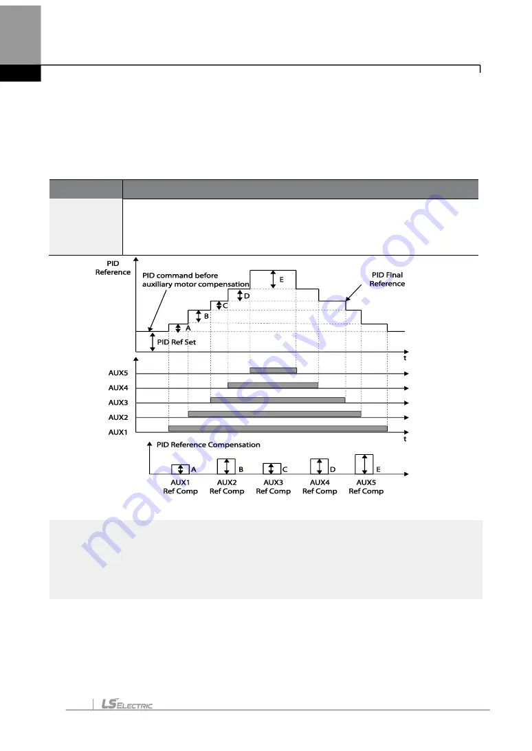
increases and the pressure of the pipe line decreases. Aux motor PID compensation
compensates for this pressure when the number of the auxiliary motor increases. By adding
the additional PID reference value (relevant to the auxiliary motor) to the current reference,
the loss of pressure can be compensated for.
Auxiliary PID Compensation Detailed Settings
Code
Description
AP1-80
–84
Aux 1
–5 Ref
Comp
Set the relevant PID reference compensation rate whenever the auxiliary
motor is turned on. The PID reference can be set over 100%, but when it
exceeds 100%, the maximum value of the PID reference is limited to 100%.
Unit band value is the value between unit 100%
–0%.
< Auxiliary motor PID compensation>
NOTE
When the aux reference value is set to 100%, the final PID reference becomes 100%. In this
case, output frequency of the inverter does not decelerate because the PID output does not
decelerate even if the input feedback value is 100%.
5.44.8 Master Follower
Summary of Contents for LSLV-H100 Series
Page 17: ...Preparing the Installation 4 37 90 kW 3 Phase ...
Page 18: ...Preparing the Installation 5 110 132 kW 3 Phase ...
Page 19: ...Preparing the Installation 6 160 185 kW 3 Phase ...
Page 20: ...Preparing the Installation 7 220 250 kW 3 Phase ...
Page 21: ...Preparing the Installation 8 315 400 kW 3 Phase ...
Page 22: ...Preparing the Installation 9 500 kW 3 Phase ...
Page 35: ...Installing the Inverter 22 ...
Page 50: ...37 Installing the Inverter Input and Output Control Terminal Block Wiring Diagram ...
Page 104: ...91 Learning Basic Features 0 10 V Input Voltage Setting Details V1 Quantizing ...
Page 181: ...168 Learning Advanced Features PID Command Block ...
Page 182: ...169 Learning Advanced Features ...
Page 183: ...170 Learning Advanced Features PID Feedback Block ...
Page 184: ...171 Learning Advanced Features PID Output Block ...
Page 185: ...172 Learning Advanced Features PID Output Mode Block ...
Page 198: ...185 Learning Advanced Features EPID1 Control block ...
Page 199: ...186 Learning Advanced Features EPID2 Control block ...
Page 220: ...207 Learning Advanced Features ...
Page 235: ...222 Learning Advanced Features The Time Chart for the Exception Day ...
Page 506: ...Table of Functions 493 ...
Page 520: ...Table of Functions 507 8 16 4 Cooling Tower MC4 Group ...
Page 549: ...Troubleshooting 536 ...
Page 569: ...Technical Specification 556 11 3 External Dimensions 0 75 30 kW 3 phase 37 90 kW 3 phase ...
Page 570: ...Technical Specification 557 110 185 kW 3 phase ...
Page 601: ...588 ...
Page 602: ...589 ...
Page 603: ...590 ...