RS-485 Communication Features
340
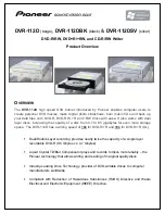
7.2 Communication System Configuration
In an RS-485 communication system, the PLC or computer is the master device and the
inverter is the slave device. When using a computer as the master, the RS-232 converter
must be integrated with the computer, so that it can communicate with the inverter through
the RS-232/RS-485 converter. Specifications and performance of converters may vary
depending on the manufacturer, but the basic functions are identical. Please refer to the
converter manufacturer’s user manual for details about features and specifications.
Connect the wires and configure the communication parameters on the inverter by referring
to the following illustration of the communication system configuration.
7.2.1 Communication Line Connection
Make sure that the inverter is turned off completely, and then connect the RS-485
communication line to the S+/S-/SG terminals of the terminal block. The maximum number
of inverters you can connect is 16. For communication lines, use shielded twisted pair
(STP) cables.
The maximum length of the communication line is 1,200 meters, but it is recommended to
use no more than 700 meters of communication line to ensure stable communication.
Please use a repeater to enhance the communication speed when using a communication
line longer than 1,200 meters or when using a large number of devices. A repeater is
effective when smooth communication is not available due to noise interference.
When wiring the communication line, make sure that the SG terminals on the PLC and
inverter are connected. SG terminals prevent communication errors due to electronic noise
interference.
Summary of Contents for LSLV-H100 Series
Page 17: ...Preparing the Installation 4 37 90 kW 3 Phase ...
Page 18: ...Preparing the Installation 5 110 132 kW 3 Phase ...
Page 19: ...Preparing the Installation 6 160 185 kW 3 Phase ...
Page 20: ...Preparing the Installation 7 220 250 kW 3 Phase ...
Page 21: ...Preparing the Installation 8 315 400 kW 3 Phase ...
Page 22: ...Preparing the Installation 9 500 kW 3 Phase ...
Page 35: ...Installing the Inverter 22 ...
Page 50: ...37 Installing the Inverter Input and Output Control Terminal Block Wiring Diagram ...
Page 104: ...91 Learning Basic Features 0 10 V Input Voltage Setting Details V1 Quantizing ...
Page 181: ...168 Learning Advanced Features PID Command Block ...
Page 182: ...169 Learning Advanced Features ...
Page 183: ...170 Learning Advanced Features PID Feedback Block ...
Page 184: ...171 Learning Advanced Features PID Output Block ...
Page 185: ...172 Learning Advanced Features PID Output Mode Block ...
Page 198: ...185 Learning Advanced Features EPID1 Control block ...
Page 199: ...186 Learning Advanced Features EPID2 Control block ...
Page 220: ...207 Learning Advanced Features ...
Page 235: ...222 Learning Advanced Features The Time Chart for the Exception Day ...
Page 506: ...Table of Functions 493 ...
Page 520: ...Table of Functions 507 8 16 4 Cooling Tower MC4 Group ...
Page 549: ...Troubleshooting 536 ...
Page 569: ...Technical Specification 556 11 3 External Dimensions 0 75 30 kW 3 phase 37 90 kW 3 phase ...
Page 570: ...Technical Specification 557 110 185 kW 3 phase ...
Page 601: ...588 ...
Page 602: ...589 ...
Page 603: ...590 ...