CAUTION:
Hazardous energy is present when the compute node is connected to the power source. Always
replace the compute node cover before installing the compute node.
If you are installing a compute node model without an integrated Ethernet controller, you must install a
network interface adapter before you install the compute node in the chassis for management network
communication. For a list of supported optional devices for the compute node, see http://www.lenovo.com/
serverproven/.
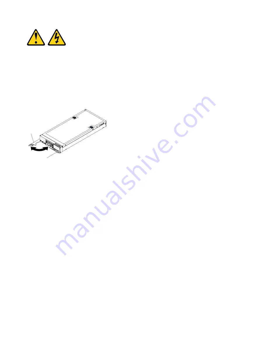
To install the compute node in a chassis, complete the following steps.
000
000
000
00000000
00000000
00000000
00000000
Label
tabs
Front
handle
Step 1.
Select the node bay.
1. If you are reinstalling a compute node that you removed, you must install it in the same node
bay from which you removed it. Some compute node configuration information and update
options are established according to node bay number. Reinstalling a compute node into a
different node bay can have unintended consequences. If you reinstall the compute node into
a different node bay, you might have to reconfigure the compute node.
2. To maintain proper system cooling, do not operate the Flex System chassis without a compute
node or node bay filler in each node bay.
Step 2.
Make sure that the front handle on the compute node is in the open position.
Step 3.
Slide the compute node into the node bay until it stops.
Step 4.
Push the front handle on the front of the compute node to the closed position.
Note:
After the compute node is installed, the IMM2 in the compute node initializes and
synchronizes with the Chassis Management Module. This process takes approximately 90
seconds. The power LED flashes rapidly, and the power button on the compute node does not
respond until this process is complete.
Step 5.
Turn on the compute node (see “Turning on the compute node” on page 15 for instructions).
Step 6.
Make sure that the power LED on the compute node control panel is lit continuously, indicating
that the compute node is receiving power and is turned on.
Step 7.
If you have other compute nodes to install, do so now.
Step 8.
You can place identifying information on the labeling tabs that are accessible from the front of the
compute node.
640
Flex System x220 Compute Node Installation and Service Guide
Summary of Contents for Flex System x220
Page 1: ...Flex System x220 Compute Node Installation and Service Guide Machine Types 7906 2585 ...
Page 50: ...42 Flex System x220 Compute Node Installation and Service Guide ...
Page 54: ...46 Flex System x220 Compute Node Installation and Service Guide ...
Page 68: ...60 Flex System x220 Compute Node Installation and Service Guide ...
Page 644: ...636 Flex System x220 Compute Node Installation and Service Guide ...
Page 698: ...690 Flex System x220 Compute Node Installation and Service Guide ...
Page 705: ...Taiwan BSMI RoHS declaration Appendix B Notices 697 ...
Page 706: ...698 Flex System x220 Compute Node Installation and Service Guide ...
Page 713: ......
Page 714: ...Part Number 00YJ297 Printed in China 1P P N 00YJ297 1P00YJ297 ...


