Chapter 17 Troubleshooting
17-103
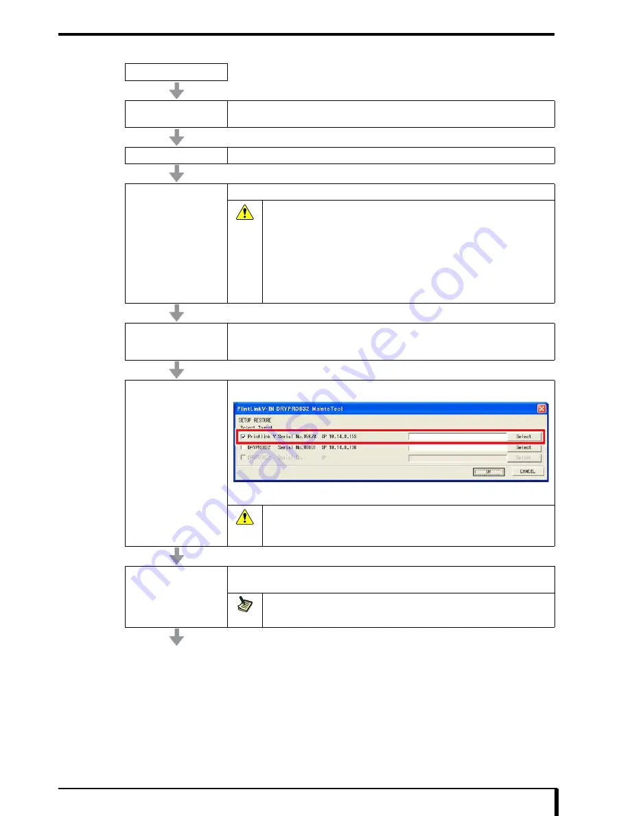
When the server PC is Printlink5-IN
START
Exit the DRYPRO 832
main unit
Refer to
“3.2.1 How to Exit” in the operation manual
to exit the DRYPRO 832 and switch the
power source breaker OFF.
Server PC Installation
Refer to
Printlink5-IN operation manual,
and install server PC.
Start the server PC
Start the server PC (Printlink5-IN).
Caution
Do not connect the DRYPRO 832 and Printlink5-IN in powered up state until
the server PCupgrade has been completed.
If you have connected the DRYPRO 832 and Printlink5-IN in powered up state
before upgrading the software, after checking following message in the
DRYPRO 832 operation panel, turn OFF the DRYPRO 832 by pressing the
operation switch, then turn OFF the power breaker directly, and then perform
the next procedure, “Upgrade of Server PC”.
•
“INITIALIZING”
Refer to operation manual for messages displayed on the operation panel.
Upgrading server PC
Refer to
“16.4 Upgrade Information (Page 16-12)”
, and upgrade the Printlink5 software to a
newer version than [V1.02R00] using the MainteTool.
If the upgrade of the server PC completes normally, the server PC will automatically restart.
Restore the setup
Refer to
“16.6 Restoring Settings (Page 16-26)”
to restore the setup.
If the restore of the server PC completes normally, the server PC will automatically restart.
Caution
Perform the restore for the Printlink5-IN. Do not restore DRYPRO 832.
If you have restored DRYPRO 832, it will be set to setting from the previous
backup. Change the setting to the one with the changes made after previous
backup.
Start the DRYPRO 832
Refer to
“3.1.1 How to Start” in the operation manual
, and check whether the DRYPRO 832
starts normally.
Note
If the MEC upgrade is performed at startup, the startup time may take a few minutes
longer than normal.
Summary of Contents for Drypro 832
Page 2: ......
Page 12: ......
Page 22: ......
Page 28: ......
Page 74: ......
Page 118: ......
Page 228: ......
Page 242: ......
Page 388: ......
Page 498: ......
Page 521: ...18 23 18 5 Block Diagram ...
Page 527: ...18 29 18 7 Printing Operation Load Timing Chart Standard 1 ch ...
Page 529: ......


