


Chapter 15 DRYPRO 832 Utility Tool
15-4
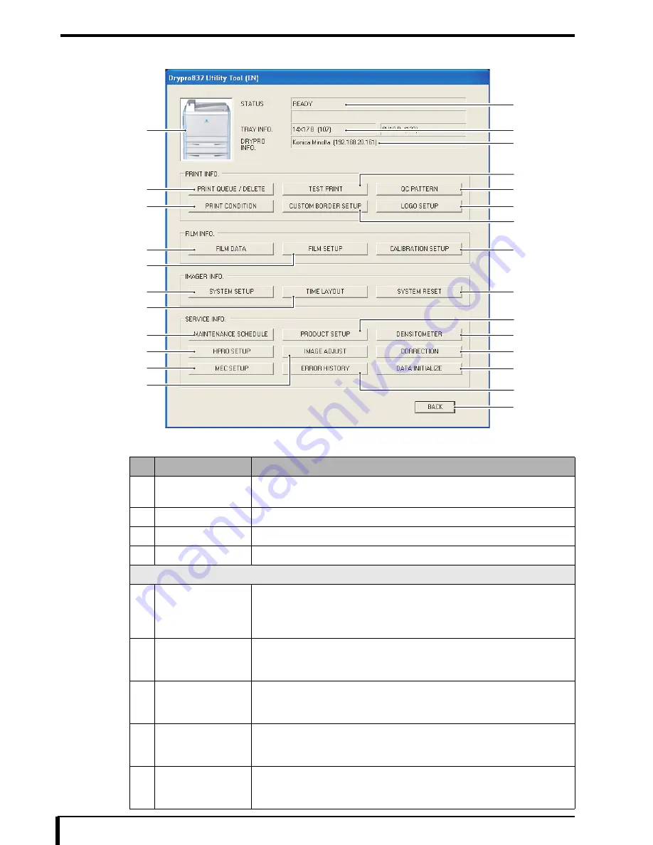
DRYPRO 832 Utility Tool - Maintenance Menu Window (Service Level Authority)
The following items are shown in the Maintenance Menu window of the DRYPRO 832 Utility Tool.
No.
Item
Description of Setting
1
DRYPRO 832
Icon
Click when an error occurs to view the “Countermeasures” window.
2
STATUS
The currently status of the device is displayed.
3
TRAY INFO.
The size and type of the packaged film will be displayed.
4
DRYPRO INFO.
The name and IP address that are set will be displayed.
PRINT INFO
5
[PRINT QUEUE /
DELETE] button
When this button is clicked, the “PRINT QUEUE/DELETE” window will appear,
and the status and other information for each print job in the DRYPRO 832 can be
confirmed, or the print job may be deleted.
For more information, see
“15.2 Print Queue/Delete (Page 15-7)”
.
6
[PRINT
CONDITION] button
When clicked, the “PRINT CONDITION” window will be displayed, and the
print conditions for each connected diagnostic device can be set.
For more information, see
“15.3 Print Condition (Page 15-9)”
.
7
[TEST PRINT]
button
When clicked, the “TEST PRINT” window opens, and various patterns can be
printed.
For more information, see
“15.4 Test Print (Page 15-12)”
.
8
[CUSTOM BORDER
SETUP] button
When clicked, the “CUSTOM BORDER SETUP” window opens, and the border
size of the film can be set.
For more information, see
“15.5 Custom Border Setup (Page 15-14)”
.
9
[QC PATTERN]
button
When clicked, the “QC PATTERN” window will open, and the standard values
and results of the QC pattern can be confirmed.
For more information, see
“15.6 QC Pattern (Page 15-15)”
.
5
1
6
17
18
19
11
9
10
2
3
4
13
23
24
25
26
16
22
8
7
20
12
14
15
21
Summary of Contents for Drypro 832
Page 2: ......
Page 12: ......
Page 22: ......
Page 28: ......
Page 74: ......
Page 118: ......
Page 228: ......
Page 242: ......
Page 388: ......
Page 498: ......
Page 521: ...18 23 18 5 Block Diagram ...
Page 527: ...18 29 18 7 Printing Operation Load Timing Chart Standard 1 ch ...
Page 529: ......


