


6
6
1
9
KEB COMBIVERT F5-M / S
Name: Basis
12.05.04
Section
Page
Date
©
KEB Antriebstechnik, 2002
All Rights reserved
Chapter
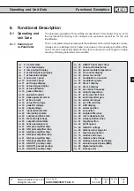
Functional Desription
Operating and Unit Data
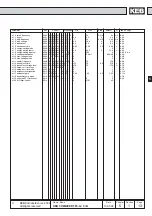
Adr.
min
max
default
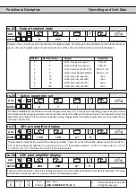
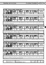
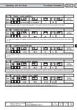
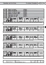
0211h
ru.17
Active current
0,1
A
-
3276,7
- 3276,7
Display of the torque-forming active current (stator losses already deducted). Negative current corresponds to generatoric
operation, positive current corresponds to motoric operation. The more precise the input of the motor data , the more
precise the indication of the active current. The maximum values depend on the size of the inverter.
Adr.
min
max
default
Adr.
min
max
default
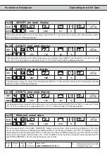
0212h
ru.18
Actual DC voltage
1
V
-
1000
0
Display of actual DC-link voltage in volt. Typical values:
Normal operation:
230V
-class 300-330V
over volt. (E.OP): approx. 400V
under volt. (E.UP): approx. 216V
400V
-class 530-620V
approx. 800V
approx. 240V
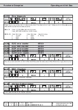
0213h
ru.19
Peak DC voltage
1
V
-
1000
0
ru.19 allows the detection of short-time peak DC voltage during an operating cycle. For that the highest detected value
of ru.18 is stored in ru.19. The peak value memory is cleared by pressing the keys UP, DOWN or ENTER or by bus by
writing any chosen value to the address of ru.19. The disconnection of the inverter also results in a clearing of the
memory.
Adr.
min
max
default
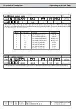
0214h
ru.20
Output voltage
1
V
-
778
0
Display of actual output voltage.