


Parameter
5
1
11
KEB COMBIVERT F5-G / C / B
Name: Basis
10.05.04
Section
Page
Date
©
KEB Antriebstechnik, 2002
All Rights reserved
Chapter
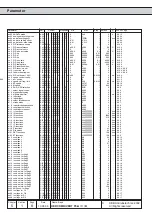
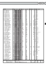
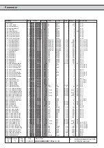
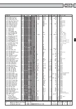
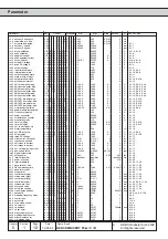
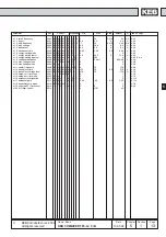
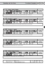
Parameter
Adr.
Control Properties min.
max.
Step default [?] see on Page
5
op53 motorpoti min. value
03 35 B C g G M S A - - - - -100,00
100,00
0,01
0,00
%
6.9.8
op54 motorpoti max. value
03 36 B C g G M S A - - - - -100,00
100,00
0,01
100,00
%
6.9.8
op55 motorpoti reset value
03 37 B C g G M S A - - - - -100,00
100,00
0,01
0,00
%
6.9.7
op56 Eing.wahl MPoti erhˆhen
03 38 B C g G M S A - - E - 0
4095
1
0
-
6.3.8, 6.9.8
op57 mot.poti dec. input sel.
03 39 B C g G M S A - - E - 0
4095
1
0
-
6.9.8, 6.3.8
op58 mot.poti reset inp. sel.
03 3A B C g G M S A - - E - 0
4095
1
0
-
6.9.8, 6.3.8
op59 motorpoti inc/dec time
03 3B B C g G M S A - - - - 0,00
50000,00
0,01
66,00
s
6.9.8
op60 dir. forward input sel.
03 3C B C g G M S A - - E - 0
4095
1
4
-
6.3.8, 6.4.7
op61 dir. reverse input sel.
03 3D B C g G M S A - - E - 0
4095
1
8
-
6.3.8, 6.4.7
op62 acc/dec time factor
03 3E B C g G M S A - - E - 0
4
1
0
-
6.4.13
pn 0 auto retry UP
04 00 B C g G M S A - - - - 0
1
1
1
-
6.7.7
pn 1 auto retry OP
04 01 B C g G M S A - - - - 0
1
1
0
-
6.7.7
pn 2 auto retry OC
04 02 B C g G M S A - - - - 0
1
1
0
-
6.7.7
pn 3 E. EF stopping mode
04 03 B C g G M S A - - - - 0
6
1
0
-
6.7.10
pn 4 ext. fault input select
04 04 B C g G M S A - - E - 0
4095
1
64
-
6.7.9, 6.3.8
pn 5 E.buS stopping mode
04 05 B C g G M S A - - - - 0
6
1
6
-
6.7.10, 11.2.3
pn 6 watchdog time
04 06 B C g G M S A - - E - 0,00:off
10,00
0,01
0,00:off
s
6.7.10, 11.2.3
pn 8 warning OL stop. mode
04 08 B C g G M S A - - - - 0
6
1
6
-
6.7.11, 6.3.15
pn 9 OL warning level
04 09 B C g G M S A - - - - 0
100
1
80
%
6.7.10
pn10 warning OH stop. mode
04 0A B C g G M S A - - - - 0
6
1
6
-
6.7.11, 6.3.15
pn11 OH warning level
04 0B B C g G M S A - - - - 0
90
1
70
∞
C
6.7.11
pn12 warning dOH stop. mode
04 0C B C g G - - - - - - - 0
7
1
7
-
6.7.11, 6.3.15, 6.7.18
pn13 E.dOH delay time
04 0D B C g G - - - - - - - 0
120
1
10
s
6.7.11, 6.7.18
pn14 warning OH2 stop. mode
04 0E B C g G M S A - - - - 0
6
1
6
-
6.7.12, 6.7.17, 6.3.15
pn16 warning OHI stop. mode
04 10 B C g G M S A - - - - 0
7
1
7
-
6.7.12, 6.3.16
pn17 E.OHI delay time
04 11 B C g G M S A - - - - 0
120
1
0
s
6.7.12
pn18 E.Set stopping mode
04 12 B C g G M S A - - - - 0
6
1
0
-
6.7.12
pn19 stall mode
04 13 - C - G M - - - P E - 0
255
1
0
-
6.7.5
pn19 stall mode
04 13 B - g - - - A - P E - 0
127
1
0
-
6.7.5
pn20 stall level
04 14 B C g G M - A - P - - 0
200
1
200:off
%
6.7.6
pn21 stall acc/dec time
04 15 B C g G M - A - P - - 0
300,00
0,01
2,00
s
6.7.6
pn22 LAD stop function
04 16 B C g G M S A - P E - 0
7
1
1 / 0
-
6.7.3
pn23 LAD stop input selection
04 17 B C g G M S A - - E - 0
4095
1
0
-
6.7.3, 6.3.8
pn24 LAD load level
04 18 B C g G M S A - P - - 0
200
1
140
%
6.7.3
pn25 LD voltage
04 19 B C g G M S A - P - - 200
800
1 375 / 720
V
6.7.3
pn26 speed search condition
04 1A B C g G M - - - P E - 0
15
1
8
-
6.7.7
pn27 speed search mode
04 1B B C g G M - - - - E - 0
127
1
0/88
-
6.7.7
pn28 DC braking mode
04 1C B C g G M - - - P E - 0
9
1
7
-
6.9.4
pn29 DC brake input selection
04 1D B C g G M - - - - E - 0
4095
1
128
-
6.9.4, 6.3.8
pn30 DC braking time
04 1E B C g G M - - - P - - 0,00
100,00
0,01
10,00
s
6.9.3
pn31 DC braking max. voltage
04 1F B C g G M - - - P - - 0,0
25,5
0,1
25,5
%
6.9.3
pn32 DC braking start freq.
04 20 B C g G - - - - P - V 0
400
0,0125
4
Hz
6.9.3
pn34 brake control mode
04 22 B C g G M S A - P E - 0
4
1
0
-
6.9.16
pn35 premagnetizing time
04 23 B C g G M S A - P - - 0,00
100,00
0,01
0,25
s
6.9.15
pn36 brake release time
04 24 B C g G M S A - P - - 0,00
100,00
0,01
0,25
s
6.9.15
pn37 Bremsenstrg. Startwert
04 25 B C g G - - - - P - V -20
20
0,0125
0
Hz
6.9.17
pn39 brake delay time
04 27 B C g G M S A - P - - 0,00
100,00
0,01
0,25
s
6.9.15
pn40 brake closing time
04 28 B C g G M S A - P - - 0,00
100,00
0,01
0,25
s
6.9.15
pn41 brake ctrl. stop ref.
04 29 B C g G - - - - P - V -20
20
0,0125
0
Hz
6.9.17
pn41 brake ctrl. stop ref.
04 29 - - - - M S A - P - V -600
600
0,125
0 rpm
6.9.17
pn43 min. load brake ctrl.
04 2B B C g G M S A - P - - 0
100
1
0
%
6.9.16
pn44 power off mode
04 2C B C g G M S A - - E - 0
511
1
0
-
6.9.19, 6.9.20, 6.9.23
pn45 power off start voltage
04 2D B C g G M S A - - - - 200
800
1 290 / 500
V
6.9.20, 6.9.21
pn46 power off auto st. level
04 2E B C g G M S A - - - - 50
90
1
80
%
6.9.20, 6.9.21
pn47 power off brake torque
04 2F B C g G - - - - - - - 0,0
100,0
0,1
0,0
%
6.9.21
pn48 power off restart level
04 30 B C g G - - - - - - V 0
400
0,0125
0
Hz
6.9.22
pn50 power off ref. DC volt.
04 32 B C g G - - - - - - - 200
800
1 290 / 500
V
6.9.21
pn51 power off KP DC volt.
04 33 B C g G M - - - - - - 0
32767
1
128
-
6.9.22
pn52 power off restart delay
04 34 B C g G M S A - - - - 0,00
100,00
0,01
0,00
s
6.9.23
pn53 power off KP act.curr.
04 35 B C g G - - - - - - - 0
32767
1
50
-
6.9.22
pn54 power off KI act.curr.
04 36 B C g G - - - - - - - 0
32767
1
50
-
6.9.22
pn55 power off KD act.curr.
04 37 B C g G - - - - - - - 0
32767
1
0
-
6.9.22
pn56 power off jump factor
04 38 B C g G - - - - - - - 0
800
1
100
%
6.9.20
pn57 power off KI DC volt.
04 39 - C - G M - - - - - - 0
32767
1
5
-
6.9.22
pn58 quick stop mode
04 3A B C g G - - A - - E - 0
3
1
0
-
6.7.13
pn59 quick stop level
04 3B B C g G - - - - - - - 0
200
1
200
%
6.7.13
pn60 quick stop acc/dec time
04 3C B C g G M S A - - - - 0
300,00
0,01
2,00
s
6.7.13
pn62 dOH warning level
04 3E - - - G M S A - - - - 0
200
1
100
∞
C
6.7.11
pn63 positioning delay
04 3F B C g G - - A - P - - -0,02
327,67
0,01
-0,01
s
6.9.31
pn64 set GTR7 input selection
04 40 - C - G M S A - - E - 0
4095
1
0
-
6.7.19, 6.3.8
pn65 special functions
04 41 - C - G M S A - - - - 0
7
1
0
-
6.7.20, 6.7.19, 6.7.9
pn69 GTR7 voltage
04 19 - C g G M S A
300
1000
1
380;740
V
ru 0 inverter state
02 00 B C g G M S A R - - - 0
255
1
0
-
6.1.6
ru 1 set value display
02 01 B C g G - - - R - - V -400
400
0,0125
0
Hz
6.1.6, 6.9.3
ru 2 ramp output display
02 02 B C g G - - - R - - V -400
400
0,0125
0
Hz
6.1.6
ru 3 actual frequency display
02 03 B C g G M S A R - - V -400
400
0,0125
0
Hz
6.1.6
ru 4 encoder 1 frequency
02 04 - - - G - - A R - - V -400
400
0,0125
0
Hz