


6
1
KEB COMBIVERT F5-M / S
10
Name: Basis
12.05.04
Chapter
Section
Page
Date
©
KEB Antriebstechnik, 2002
All Rights reserved
Functional Desription
Operating and Unit Data
Adr.
min
max
default
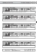
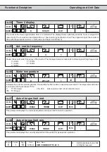
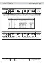
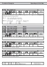
0216h
ru.22
Internal input state
1
-
-
4095
0
Display of the currently set external and internal digital inputs. The input is considered as set when it is available as
active signal for further processing (i.e. acceptance by strobe, edge triggering or logic operation). According to the table
(ru.21) a certain decimal value is given out for each digital input. If several inputs are set then the sum of their decimal
values is displayed (see Chapter 6.3 ÑDigital Inputsì).
Adr.
min
max
default
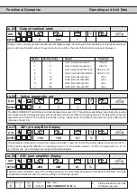
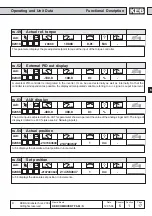
0215h
ru.21
Input terminal state
1
-
-
4095
0
Display of the current set digital inputs. The logic levels on the input terminals or on the internal inputs are indicated
regardless whether the input is inverted or the internal acceptance is effected through edge-triggering or Strobe (also
see Chapt. 6.3 ÑDigital inputsì). According to following table a specific decimal value is given out for each digital input.
If several inputs are controlled, the sum of the decimal values is indicated.
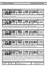
Bit -No. Decimal value
Input
Terminal
0
1
ST (prog. input Ñcontrol release / resetì)
X2A.16
1
2
RST (prog. input Ñresetì)
X2A.17
2
4
F (prog. input Ñforwardì)
X2A.14
3
8
R (prog. input Ñreverseì)
X2A.15
4
16
I1 (prog. input 1)
X2A.10
5
32
I2 (prog. input 2)
X2A.11
6
64
I3 (prog. input 3)
X2A.12
7
128
I4 (prog. input 4)
X2A.13
8
256
IA (internal input A)
none
9
512
IB (internal input B)
none
10
1024
IC (internal input C)
none
11
2048
ID (internal input D)
none