


6
9
KEB COMBIVERT F5
20
Name: Basis
04.05.04
Chapter
Section
Page
Date
©
KEB Antriebstechnik, 2002
All rights reserved
Functional Description
Special Functions
Start voltage (Pn.45)
With manual adjustment the starting voltage can be preset with Pn.45 in the range of
200...800 volt. For a secure range the adjusted starting voltage must be at least 50 V
over the UP-threshold (UP: 400V-class=240V; 200V-class=216V DC).
With automatic starting voltage the DC-link voltage is measured at „Power-On“ and is
displayed in ru.68. The actual starting voltage is determined by Pn.46, which adjusts
the starting voltage in percent in the range of 50...90 % of the measured value. The
default setting is 80%.
If the DC-link actual voltage value drops below the starting voltage, adjusted
automatically or manually, the Power-Off function is started.
Auto-Start voltage (Pn.46)
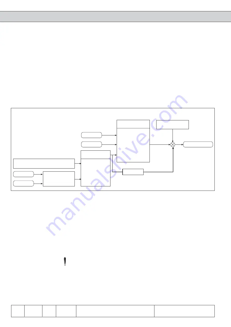
Fig. 6.9.6.b Frequency jump for generatoric operation at the 1. cycle
Frequency jump for
generatoric operation
First of all the drive must be brought into generatoric operation to enable the feed back
of energy into the intermediate circuit. This is achieved by making a frequency jump,
so that the speed of the drive is larger than the output rotating field speed of the
inverter.
With the actual value source it is defined whether the Power-Off works as slip control
(with speed detection on channel 1 or 2 value „0“ of „1“) or as active current control
(without speed detection value „2“). Normally this parameter is adusted at the setup of
the speed control (see Chapter 6.11) and should not be changed here.
The parameter Pn.44 Bit2 determines, whether the starting jump is calculated from the
slip (active current) or from the utilization. This setting has no effect on slip regulation.
The standard setting is from slip, but in the case of high harmonic content of the output
current it can lead to false values. In that case the starting jump must be determined
from the utilization. To get proper values enter motor data into
dr-parameters first.
By means of the jump factor the automatically determined starting jump can be adapted
to the respective application.
In case the jump factor is too small, the inverter trips to UP!
In case the jump factor is too high, the inverter runs into the hardware current limitation.
The control cannot work correctly, thus causing a wrong calculation of the active
current!
Enter motor data into
dr-parameters!
Load
Pn.44 Bit 2
Starting jump
0: Active current I
w
1: Load I
s
Slip calculation
Pn.56 Jump factor
0...800%
Jump factor (Pn.56)
Motor data
Slip calcullation by the active current
channel 2
channel 1
CS.1 Act. value source
0: Encoder CH1
1: Encoder CH2
2: calculated
actual
value
Frequency jump
Actual value source (CS.1)
Starting jump (Pn.44 Bit 2)
Die Zwischenkreisspannung wird immer beim Einschalten des Leistungsteils oder
nach E.UP gemessen und in ru.68 angezeigt.
Rated DC voltage (ru.68)
F5-B/C
(at F5-B/C always
active current control)