


3
Hardware
Control Cards
3
1
7
KEB COMBIVERT F5-M / S
Name: Basis
18.05.04
Section
Page
Date
©
KEB Antriebstechnik, 2002
All Rights reserved
Chapter
10
18 19 20
PE
X2A
21 22 23
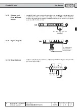
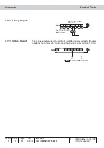
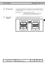
3.1.10 Relay Outputs
3.1.9
Digital Outputs
A total of max.
50 mA DC for
both outputs
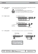
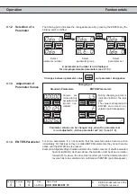
3.1.8
Voltage Input /
External Power
Supply
In case of inductive load on the relay outputs a protective wiring must be provided
(e.g. free-wheeling diode)!
The supply of the control circuit through an external voltage source keeps the control
in operational condition even if the power stage is switched off. To prevent undefined
conditions at external power supply the basic procedure is to first switch on the power
supply and after that the inverter.
24 25 26
PE
27 28 29
max.30VDC
0,01...1A
+
-
X2A
10 11
17 18 19 20
PE
X2A
21 22 23
+
20...30 V ±0% / 1 A DC
smoothed