


Functional Description
Analog In- and Outputs
2
6
6
Name: Basis
KEB COMBIVERT F5
Chapter
Section
Page
Date
04.05.04
©
KEB Antriebstechnik, 2002
All rights reserved
-10%
10%
10%
-10%
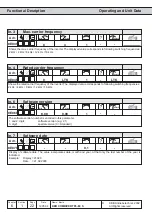
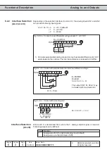
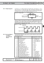
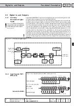
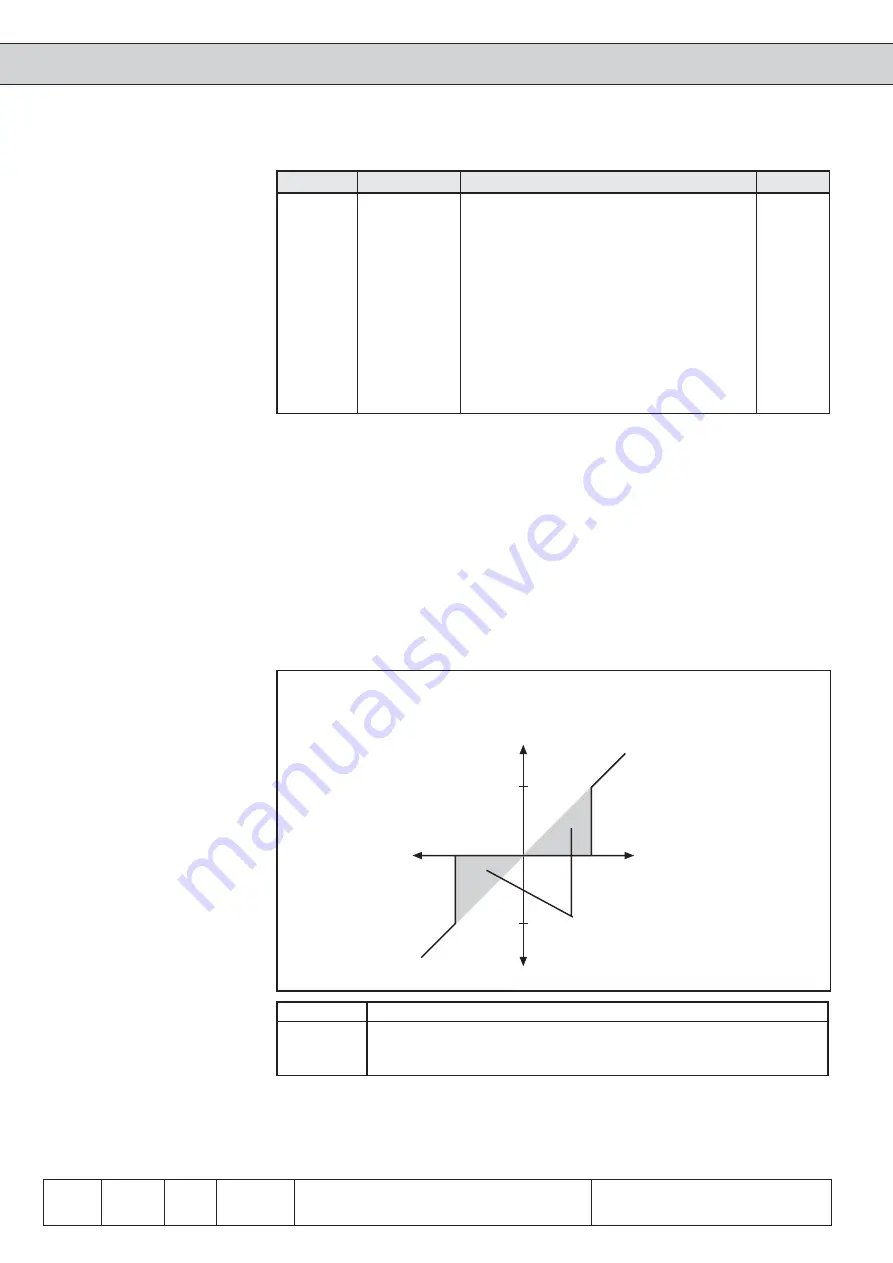
6.2.6
Zero Point Hyste-
resis (An.4;
An.14; An.24)
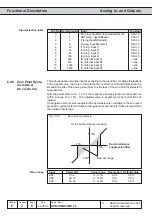
Through capacitive as well as inductive coupling on the input lines or voltage fluctuations
of the signal source, the motor connected to the inverter can still drift (tremble) during
standstill in spite of the analog input filter. It is the task of the zero point hysteresis to
suppress this.
With the parameters An.4 / 14 / 24 the respective analog signals can be faded out
within a range of 0...10% . The adjusted value is applicable for both directions of
rotation.
If a negative percent value is adjusted the hysteresis acts in addition to the zero point
around the current setpoint. Setpoint changes are accepted only if they are larger than
the adjusted hysteresis.
from interference
suppression filter
for the further signal processing
fade-out range
Input
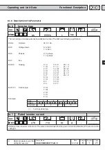
Parameter
Value range
Resolution Default value
AN1
An.4
0...±10%
0,1%
0,2%
AN2
An.14
0...±10%
0,1%
0,2%
AN3
An.24
0...±10%
0,1%
0,2%
Fig. 6.2.6
Zero point hysteresis
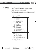
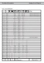
Value range
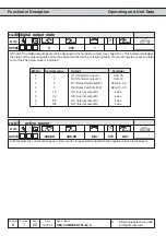
Bit -No. Decimal value
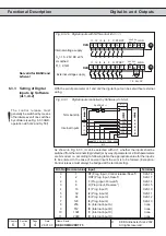
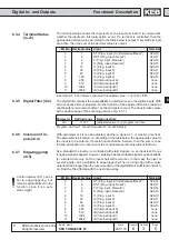
Input
Terminal
0
1
ST (prog. input Ñcontrol release/Resetì)
X2A.16
1
2
RST (prog. input ÑResetì)
X2A.17
2
4
F (prog. input Ñforwardì)
X2A.14
3
8
R (prog. input Ñreverseì)
X2A.15
4
16
I1 (prog. input 1)
X2A.10
5
32
I2 (prog. input 2)
X2A.11
6
64
I3 (prog. input 3)
X2A.12
7
128
I4 (prog. input 4)
X2A.13
8
256
IA (internal input A)
none
9
512
IB (internal input B)
none
10
1024
IC (internal input C)
none
11
2048
ID (internal input D)
none
Input selection table