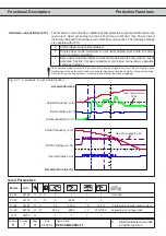


6
7
KEB COMBIVERT F5
18
Name: Basis
04.05.04
Chapter
Section
Page
Date
©
KEB Antriebstechnik, 2002
All rights reserved
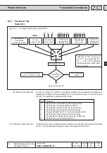
Functional Description
Protective Functions
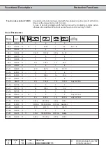
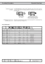
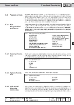
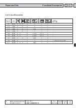
Param.
Adr.
min
max
default
ENTER
PROG.
R/W
Step
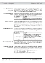
Used Parameters
fr. 8
0908h
✔
✔
-
0
7
1
0
not at F5-S
Pn.12
040Ch
✔
-
-
0
7
1
7
-
Pn.13
040Dh
✔
-
-
0
120 s
1 s
0 s
-
Pn.14
040Eh
✔
-
-
0
6
1
6
-
Pn.15
040Fh
✔
-
-
0 %
100 %
1 %
100 %
only at F5-S
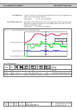
dr.11
060Bh
✔
✔
-
0
1
1
1
not at F5-S
dr.12
060Ch
✔
✔
-
0,0
710,0A
0,1A
LTK
not at F5-S
dr.34
0622
✔
-
-
0,1 s
10,0 s
0,1 s
0,5 s
only at F5-S
dr.35
0623
✔
-
-
0,1 s
10,0 s
0,1
s
0,2 s
only at F5-S
dr.36
0624
✔
-
-
0,1 s
10,0 s
0,1 s
5,0 s
only at F5-S
ru.15
020Fh
-
-
-
0,0 A
6553,5 A
0,1 A
-
-
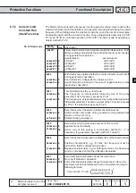
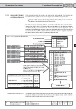
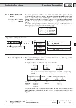
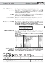
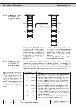
The KEB COMBIVERT provides another possibilitiy to protect the motor by connecting
an external temperature monitoring. Following components can be connected to
terminals T1/T2:
External error control
procedure
Thermo contact
(NC contact)
Temperature sensor (PTC)
1650
Ω
...4k
Ω
tripping resistance
750
Ω
...1650
Ω
reset resistance
T1
T2
T1
T2
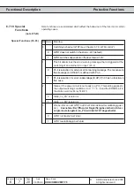
With these two parameters the behaviour of the terminals T1/T2 is determined. The
function is described in Chapter 6.7.6.
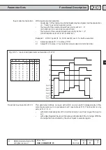
dOH stopping mode (Pn.12)
dOH delay time (Pn.13)