


6
11
KEB COMBIVERT F5-M / S
10
Name: Basis
06.05.04
Chapter
Section
Page
Date
©
KEB Antriebstechnik, 2002
All Rights reserved
Functional Desription
Positioning and Synchronous Control
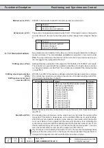
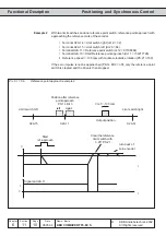
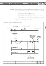
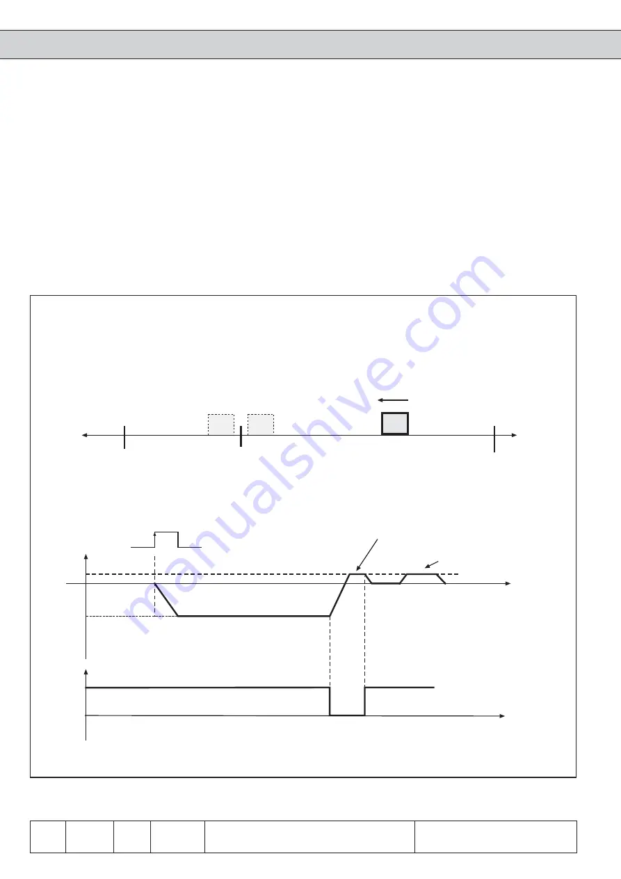
With two limit switches and one reference point switch; reference point approach with
approaching the reference mark of the encoder.
ï Terminal X2A.14 = Limit switch right (di.19 = 32)
ï Terminal X2A.15 = Limit switch left (di.20 = 64)
ï Terminal X2A.11 = Reference point switch (di.12 = 67108864)
ï Terminal X2A.10 = Start Reference point approach (di.11 = 134217728)
ï Reference speed = -100 rpm with counter-clockwise rotation (PS.21=-100)
If the zero impulse is not be approached (PS.14 Bit 2 = off), only the reference point
switch is cleared and the drive is then stopped.
Example 2
Pic. 6.11.6.b
Reference point approach example 2
V
t
t
1
0
X2A.15
X2A.14
X2A.11
Output position
Position after reference
point approach
PS.14 Bit 3
Vref = -100 rpm
Start
ref.-approach
Signal an X2A.11
Clear the reference
limit switch with
0.25* PS.21
turn back of
zero encoder
left
right
Limit switch left
Limit switch right