


6
6
KEB COMBIVERT F5-M / S
6
Name: Basis
12.05.04
Chapter
Section
Page
Date
©
KEB Antriebstechnik, 2002
All Rights reserved
Functional Desription
Motor Data and Controller
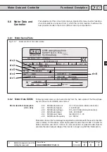
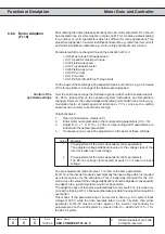
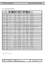
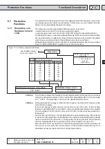
6.6.3 Motor Adaption
(Fr.10)
After entering the name plate specifications of a new motor parameter Fr.10 should
be activated once (inverter must be in status noP). This creates a default setting
for a number of control parameters which is sufficient for many applications. This
adjustment depends on inverter identification data (like e.g. rated inverter current)
and motor identification data (like e.g. motor rating and rated motor current).
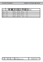
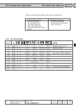
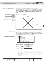
Parameters which are changed through the activation of Fr.10:
ï dr.16 Max. torque field weak speed
ï dr.17 Speed for maximum torque
ï dr.18 Field weak speed
ï dr.19 Flux adaption factor
ï dr.20 Field weak curve
ï dS.0 KP current
ï dS.1 KI current
ï CS.19/CS.20/CS.22/Pn.61 Torque limits
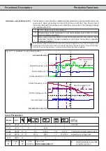
On the basis of these settings a fine adustment can be carried out, e.g. an increase
of the torque limits or a change of the field weakening speed.
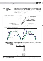
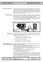
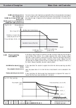
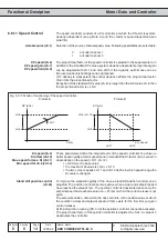
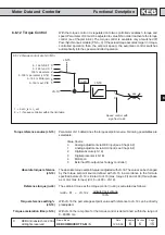
Over the entire speed range the modulation grade ru.42 should not exceed approx.
90...95†% (depending on the expected system fluctuations and temperature
changes). However, the output voltage at the rated point should not be too low (e.g.
modulation factor at rated speed and rated load < 70 %), since such a setting
would result in a motor current that is too high.
Vorgehensweise:
1.
Open control release (status noP)
2.
Enter motor name plate data in the corresponding parameters (dr.0...12).
3.
Adjust Fr.10 = 1 or Fr.10 = 2
⇒
the corresponding dr/dS parameters are
loaded with the default-parameters.
4.
If necessary, carry out a fine adjustment on the basis of these settings.
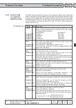
Value
Meaning
1
Pre-adjustment of the motor-dependent control-parameters
The adjusted voltage stabilization value or the voltage class of the
inverter is taken as input voltage.
2
Pre-adjustment of the motor-dependent control-parameters
The DC-link voltage /
√
2 measured at switch on is taken as input
voltage.
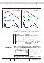
The pre-adjustments made at value 1 or 2 refer to the same parameters.
For Fr.10=2 the inverter measures automatically the input voltage which is required
as reference value for the calculation. This is especially important for the CP-
mode, since the value for the voltage stabilization cannot be adjusted, consequently
an adaption to e.g. 460V-systems would not be possible.
The adaption does not take place automatically at every switch on, it is done only
once at the tripping of Fr.10 because otherwise possible fine adjustment would be
overwritten.
This means: If the parameterizing of an inverter is done e.g. at a system input
voltage of 400 V, while the drive operates later on a 460 V system, then either
parameter Fr.10†=†2 must be written again or the inverter must already be
parameterized on the 400V-system by means of dS.10 = 460V and Fr.10 = 1 for
the 460 V system.
Control of the
optimized settings