


6
10
KEB COMBIVERT F5
8
Name: Basis
17.02.03
Chapter
Section
Page
Date
©
KEB Antriebstechnik, 2002
All rights reserved
Functional Description
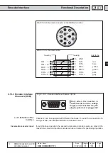
Encoder Interface
1000
10000
1000
10000
200 kHz
300 kHz
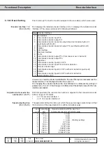
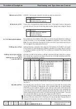
6.10.5 Selection of
Encoder
Precondition for a good control behaviour of the drive is not least a question of the
selection and the correct connection of the encoder. This also includes the mechanical
as well as the electrical connection.
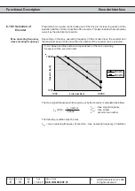
Max. operating frequency
(max.sampling frequency)
Depending on the max. operating frequency of the encoder input, the encoder and
the maximum speed of the drive the line number of the encoder can be selected.
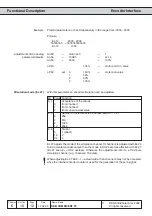
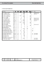
6.9.4 Speed and line number in dependence on the max. operating
frequency of the encoder inputs
Speed n [rpm]
Line number z
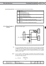
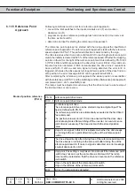
The max. signal frequency, which is given out by the encoder, is calculated as follows:
n
max
[rpm] x z
60000
f
max
[kHz] =
f
max
: max. signal frequency
n
max
: max. speed
z:
encoder line number
The following condition must be met:
f
max
< max. operating frequency of encoder < max. operating frequency of interface