


6
6
11
19
KEB COMBIVERT F5-M / S
Name: Basis
06.05.04
Section
Page
Date
©
KEB Antriebstechnik, 2002
All Rights reserved
Chapter
Functional Desription
Positioning and Synchronous Control
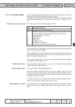
In the contouring mode positions are preset within a fixed time pattern. The inverter
takes over the fine interpolation and the position control.
The adjustment of the speed setpoint is done over SERCOS or by position settings
with 32 bit position setpoints. The setpoints can be preset in a pattern of min. 1
ms.
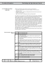
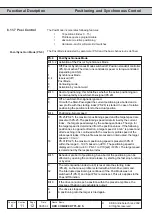
The contouring mode is activated by parameter PS.0.
PS.0
Posi/Synchron Mode
Bit 0...2 Activation of Posi or Synchron mode
0
Off; Posi or Synchron mode switched off; position standstill controller
(PS.6) not active. The drive runs controlled, speed- or torque-
controlled (dependent on CS.0).
1
Synchron mode
2..4
reserved (off)
5
Posi mode
6
Contouring mode
7
Activation by control word
Bit 3...10 reserved for posi and synchronous module
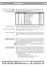
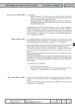
Changing into the contouring mode and from the contouring mode into the positioning
mode is only possible at standstill.
When activating the synchron mode over the bus operator, the cycle time is
automatically adjusted in Sy.08. If the contouring mode was activated, the inverter
status ru.0 changes to ÑPosi activeì.
The changeover between posi-, synchron- and contouring mode is also possible by
the control word (see chapter 11.2.7).
The process data must be adjusted in such a way, that the position setpoint for the
contouring mode is written to PS.34.
The actual position value is displayed in ru.54.
Before the operator activates the synchron mode, operator and control card
synchronize. Now the actual position must already be written cyclically to PS.34.
After the contouring mode was activated, it must be written continously with the
constanst cycle time on PS.34.
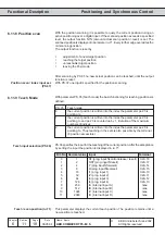
The maximum speed in the contouring mode is limited only by the absolute maximum
speeds in oP.14 and oP.15. The torque limits are active.
The contouring error in the contouring mode can be viewed in ru.58. This value can
also be monitored over a digital output with the switching condition 39 : angle >
level.
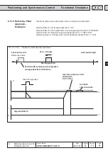
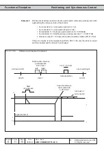
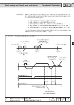
6.11.10 Contouring Mode
Activation of contouring mode
CTM Position (PS.34)
Actual position (ru.54)
Angular difference (ru.58)