


6
7
KEB COMBIVERT F5
4
Name: Basis
04.05.04
Chapter
Section
Page
Date
©
KEB Antriebstechnik, 2002
All rights reserved
Functional Description
Protective Functions
Param.
Adr.
min
max
default
ENTER
PROG.
R/W
Step
A
B
C
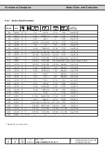
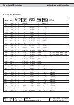
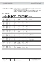
Used Parameters
Pn.22
0416h
✔
✔
✔
0
7
1
1
bit-coded
Pn.23
0417h
✔
-
✔
0
4095
1
0
-
Pn.24
0418h
✔
✔
-
0 %
200 %
1 %
140 %
% referring to inverter rated current
Pn.25
0419h
✔
✔
-
200 V
800 V
1 V
375/720 V
depending on voltage class
uF.15
050Fh
✔
-
-
0
2
1
1
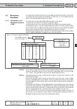
-
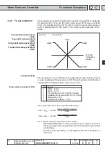
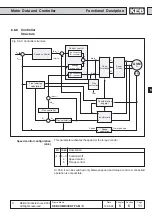
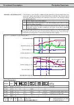
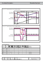
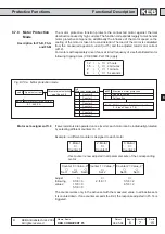
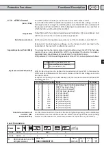
Fig. 6.7.1.b Example for ramp stop function
Actual frequency (ru.3)
Inverter status (ru.0)
Actual utilization (ru.13)
max. ramp current
Pn.24
Acceleration stop
Actual frequency (ru.3)
Inverter status (ru.0)
DC-link voltage (ru.18)
Deceleration stop (U)
max. DC-voltage Pn.25
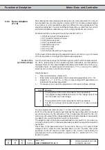
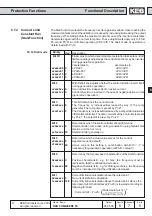
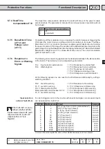
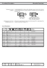
0
off; Hardware current limit disabled
1
Single phase mode; Hardware current limit enabled; works both in motoric
and generatoric operation
2
Zero vektor mode; Hardware current limit enabled; works only motoric, but at
activated function it makes available more torque. Generatoric operation
switches to Mode 1.
The hardware current limit is an additional, fast protection to prevent faults caused by
overcurrent. Upon exceeding the max. short-time current limit (see Power Circuit
Instruction Manual) the hardware current limit becomes active. The following settings
are possible with uF.15:
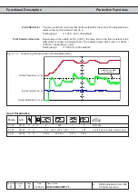
The hardware current limit limits the current at the limit and triggers no error. This can lead to torque
breakdowns at the motor shaft, which is especially important during the operation „lifting and lowering“
since the drive can sag because of missing torque without the brake engaging.
Hardware current limit (uF.15)