


6
10
13
KEB COMBIVERT F5
Name: Basis
17.02.03
6
Section
Page
Date
©
KEB Antriebstechnik, 2002
All rights reserved
Chapter
Functional Description
Encoder Interface
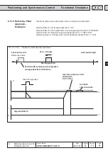
This parameter exists only at F5-S. The system position of the attached resolver
system is adjusted (factory setting).
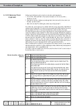
With this parameter it is possible to adjust the controller to a not aligned motor. If the
system position of the motor is unknown an automatic trimming can carried out.
Before starting with the adjustment, the direction of rotation must be checked. The
speed display (ru.9) must be positive in the case of clockwise rotation by hand. If that
is not the case, the direction of rotation can be exchanged with Ec.6 as described.
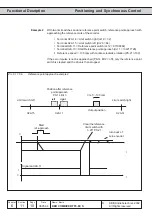
ç enter motor data
ç the connected motor must be able to rotate freely
ç open control release
ç enter Ec.2/12 = 2206
ç close control release
The motor is excited now with its rated current.
If the direction of rotation of the connected motor is not correct or two motor phases
are exchanged, E.EnC is triggered.
For resolver sytems the signal SIN+ and SIN- must be exchanged.
If the system postion displayed in Ec.2/12 no longer changes the alignment is
completed.
ç open control release
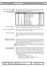
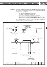
If motors with aligned encoder systems are used, the value determined by the
automatic alignment can be entered directly in Ec.2/12.
Absolute position channel 1/
2
(Ec.2 / Ec.12)
(only F5-S)
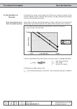
In order to replace S4-systems by F5-S the following calculation must be carried out:
ec.7 ( S4) * Pole pair number
- Furthermore pay attention to the encoder cable -
- The lower 16 Bit of the result must be entered in Ec.2/12 -
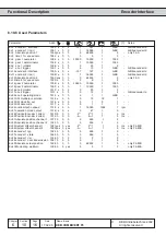
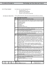
6.10.7 Additional
Parameters
The following parameters are needed only for specific encoder interfaces and are
explained more closely in the appropriate documentation.
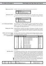
If an SSI-multiturn-absolute value encoder is connected, the number of the bits for
the multiturn-resolution can be adjusted here (12 Bit).
The clock frequency of the SSI-encoder is adjusted in Ec.22. Two clock frequencies
are available 0 : 312,5 kHz or 1 : 156,25 kHz. The smaller clock frequency should
only be adjusted for long cables or in case interferences occur.
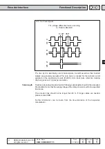
The unit supports two data formats for the SSI-encoders:
0 : binary coded
1 : Gray code
As reference speed the max. tachometer speed is adjusted in Ec.25.
Position value directly from encoder channel 1 / 2 (with complete revolutions).
Ec.31 and Ec.32 show the position values of channel 1 and 2 after the gearbox.
SSI Multiturn resolution
(Ec.21)
SSI Clock frequency select
(Ec.22)
SSI Data code (Ec.23)
Nominal tacho speed (Ec.25)
Position channel 1 direct
(Ec.29)
Position channel 2 direct
(Ec.30)
Position Channel 1 (Ec.31)
Position Channel 2 (Ec.32)