


19
6
3
19
KEB COMBIVERT F5
Name: Basis
28.01.03
6
Section
Page
Date
©
KEB Antriebstechnik, 2002
All rights reserved
Chapter
Functional Description
Digital In- and Outputs
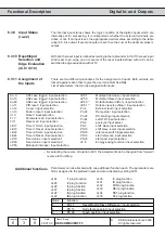
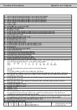
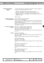
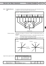
6.3.25 Programming
Example
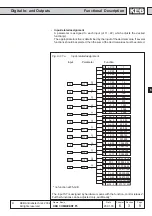
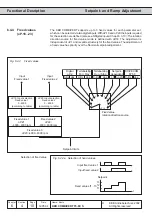
For a better understanding, the correlations are explained on the basis of a little more
complex example. Following conditions are required:
• Condition 1: Output X2A.19 switches, if the inverter accelerates
• Condition 2: Relais X2A.24...26 switches, if the inverter load is > 100 %
• Condition 3: Relais X2A.27...29 switches, if the actual frequency is > 4 Hz
• Output X2A.18 switches, if the conditions 2 and 3 are realized, but the inverter
does not accelerate.
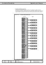
Solution proposal:
First set the switching conditions and levels.
Set do.0 to „21“ (inverter accelerates)
Set do.1 to „24“ (inverter utilization > level); set LE.1 to „100“ (load level for do.1
100 %); set LE.9 to „5“ (5 % hysteresis for level 1; not required but reasonable for
optimal switching performance)
Set do.2 to „27“ (actual frequency > level); set LE.2 to „4“ (frequency level for do.2=4 Hz);
set LE.10 to „0.5“ (0.5 Hz hysteresis for level 3; not required but reasonable for opti-
mal switching performance)
Set do.16 to „1“ (evaluate switching condition of do.0)
Set do.17 to „2“ (evaluate switching condition of do.1)
Set do.18 to „4“ (evaluate switching condition of do.2)
Set do.8, do.9 and do.10 to „0“ (no inverting)
The setting of do.24 is independent for this example, as only one condition each is set
at do.16...18.
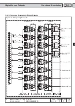
Output O1 (terminal X2A.18)
Set do.33 to „7“ (evaluate flags 1...3)
Set do.25 to „1“ (flag 1 is inverted, it means that the condition is fulfilled if the inverter
does not accelerate.
Set do.41 to „1“ (the conditions selected with do.33 become AND-operated)
Output O2 (terminal X2A.19)
Set do.34 to „1“ (evaluate flag 1)
Set do.26 to „0“ (no inverting)
The setting of do.41 is independent for this example, as only one condition is set at
do.34.
Relay output R1 (terminal X2A.24...26)
Set do.35 to „2“ (evaluate flag 2)
Set do.27 to „0“ (no inverting)
The setting of do.41 is independent for this example, as only one condition is set at
do.35.
Relay output R2 (terminal X2A.27...29)
Set do.36 to „4“ (evaluate flag 3)
Set do.28 to „0“ (no inverting)
The setting of do.41 is independent for this example, as only one condition is set at
do.36.
Set switching conditions,
levels and hysteresis
Set switching conditions
of stage 1
Set flags