


6
3
KEB COMBIVERT F5
12
Name: Basis
28.01.03
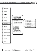
Chapter
Section
Page
Date
©
KEB Antriebstechnik, 2002
All rights reserved
Functional Description
Digital In- and Outputs
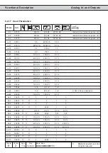
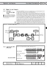
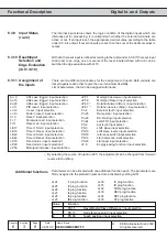
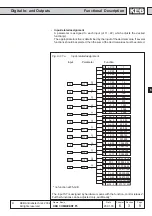
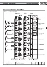
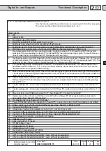
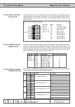
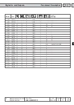
For the switching of the digital outputs one can choose up to 8 conditions from the 69
different conditions. These are entered in do.0...do.7. Switching condition 0 and 1 can
be filtered by do.43 and do.44. Parameter ru.23 shows, if one or several of these
conditions are met. For each channel it can now be selected which of the 8 conditions
shall apply to it (do.16...do.23). Each condition can still be inverted before selection
(do.8...do.15). As a standard all conditions (if several are selected) are OR-operated,
i.e. if one of the selected conditions is fulfilled, the channel is set. With do.24 this can
be changed to AND-operation, i.e. all conditions selected for this channel must be
fulfilled before it is set. Parameter ru.24 shows the channels which are set in this
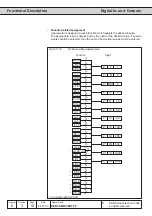
stage. do.33...40 form a second logic step with which a selection of the channels from
logic step 1 can be made. Every individual condition can be inverted with do..25...32.
do.41 adjusts the manner of the linkage (AND/OR). Parameter do.42 is used for inverting
one or several outputs.With do.51 the output signals are assigned to the terminals.
ru.80 serves for the display of the status prior to allocation, thereafter ru.25. The internal
outputs OA...OD are directly connected with the internal inputs IA...ID.
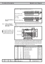
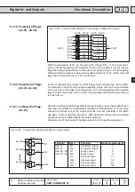
6.3.13 Output Signals
Fig. 6.3.12
Connection of digital outputs
The total current of
X2A.18...20 is limited to
50mA. In case of inductive load
at the relay outputs or at the
transistor output a protective
wiring is to be provided (free-
wheeling diode)!
24 25 26
RLA RLB RLC
X2A
max. 30V / 1A DC
R1
19
23
20
O2
0V
U
out
X2A
+24V / 50mA
R2
27 28 29
FLA FLB FLC
max. 30V / 1A DC
18
O1
X2A
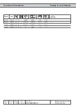
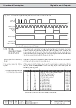
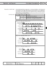
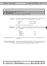
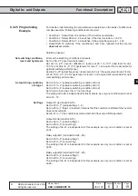
6.3.14 Output filter
(do.43, do.44)
With do.43 a filter can be set for switching condition 0, with do.44 for switching condition
1. The change of a switching condition must be applied for the filter time, then it
becomes active at the output of the filter. If the change of a switching condition is
cancelled during the filter time, the filter time is reset and restarted at the next change.
The filter time is adjustable within the range of 0 (off)...1000 ms.
Description