


6
6
6
5
KEB COMBIVERT F5-M / S
Name: Basis
12.05.04
Section
Page
Date
©
KEB Antriebstechnik, 2002
All Rights reserved
Chapter
Functional Desription
Motor Data and Controller
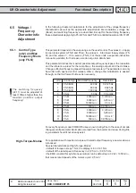
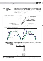
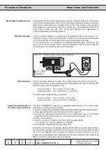
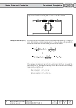
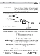
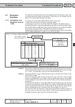
Leakage Inductance (dr.7)
R
1
X
1
σ
X
2
σ
’
R
2’
X
h
R
Fe
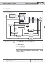
Fig. 6.6.3 Equivalent circuit diagram of a motor in phase quantities
σσσσσ
L
S
=
1
(
(X
1
σσσσσ
+ X
h
) -
X
h
≤
)
ω
ω
ω
ω
ω
(X
2
σσσσσ
í
+ X
h
)
σσσσσ
L
S
= (L
1
σσσσσ
+ L
h
)
-
(L
h
≤
)
2
≈≈≈≈≈
L
1
σσσσσ
+
L
2
σσσσσ
í
(L
2
σσσσσ
í
+ L
h
)
In accordance with the following formula the leakage inductance
σ
L
S
in a range of
0,00...500,00 mH is entered in parameter dr.7. In case the data is not specified in
the data sheet the motor manufacturers give further information.
or
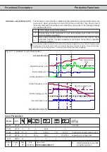
If the leakage inductance is taken from a data sheet, then there is usually the
phase value for
σ
L
S
specified. Depending on the used connection the following
value must be entered in dr.7:
Star connection:
dr.7 = 2 x
σ
L
S
Delta connection: dr.7 = 2/3 x
σ
L
S