


Functional Description
Analog In- and Outputs
2
4
6
Name: Basis
KEB COMBIVERT F5
Chapter
Section
Page
Date
04.05.04
©
KEB Antriebstechnik, 2002
All rights reserved
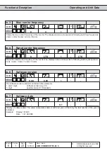
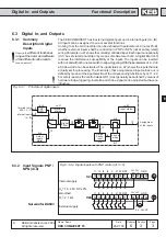
X2A.
1 2 3 4 5 6 7 8 9
R = 3...10 k
W
PE
0...10V DC
Ri=30k
Ω
(An.0 / An.10 = 0)
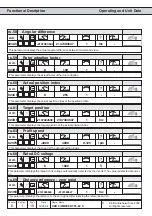
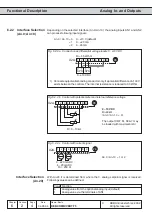
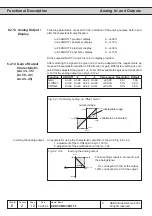
6.2.2
Interface Selection
(An.0; An.10)
Fig. 6.2.2.a Connection as differential voltage inputs 0...±10V DC
The output CRF Kl. X2A.7 may
be loaded with maximal 6mA!
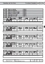
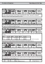
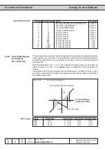
Depending on the selected interface (An.0/An.10) the analog inputs AN1 and AN2
can process following input signals:
An.0 / An.10= 0
0...±10 V (default)
= 1
0...±20 mA
= 2
4...20 mA
Fig. 6.2.2.b Control with potentiometer and internal reference voltage
X2A.
1 2 3 4 5 6 7 8 9
PE
0...±10 VDC
+
-
SPS
+
-
SPS
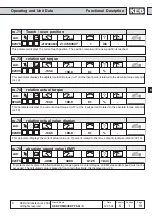
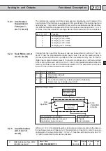
1)
1) Connect equipotential bonding conductor only, if a potential difference of >†30V
exists between the controls. The internal resistance is reduced to 30 kOhm.
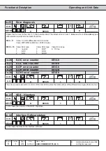
X2A.
1 2 3 4 5 6 7 8 9
+
0...±20 mADC
4...20 mADC
Ri = 250
Ω
PE
+
An.0 / An.10 = 1 or 2
Fig. 6.2.2.c Control with current signal
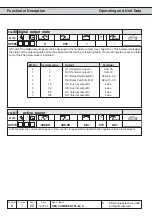
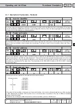
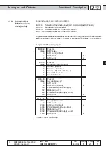
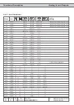
Interface Selection
(An.20)
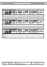
With An.20 it is determined from where the 3. analog setpoint signal is received.
Following values can be defined:
Value Function
0
Analog value from the optional analog input (default)
1
Analog value via the terminals of AN1
Ri = 55 kOhm