


6
5
5
KEB COMBIVERT F5
Name: Basis
04.05.04
6
Section
Page
Date
©
KEB Antriebstechnik, 2002
All rights reserved
Chapter
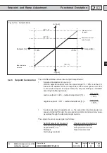
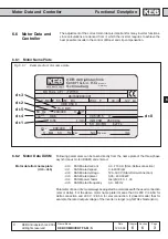
Functional Description
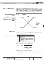
U/f-Characteristic Adjustment
250 V
190 V
CP.17=230 V
CP.16=50 Hz
U
N
/U
A
f
uF.9 = 230V
uF.0 = 50Hz
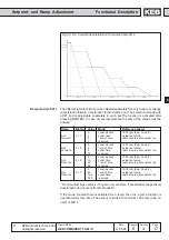
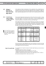
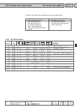
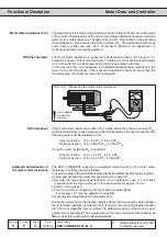
6.5.5
Voltage
Stabilization
(uF.9)
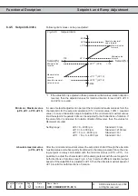
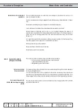
Due to fluctuations of the mains voltage or the load the DC-link voltage and with it the
directly dependent output voltage can change. In the case of enabled voltage
stabilization the fluctuations of the output voltage are compensated. That means 100%
output voltage correspond to the value adjusted in uF.9, but maximally 110 % · (DC-
link voltage /
√
2 ). Furthermore, this function makes it possible to adapt motors with
a smaller rated current to the inverter.
uF.9 = 1...649 V
650 = off (default)
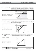
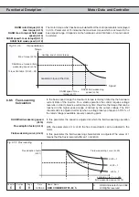
Fig. 6.5.5.a Voltage stabilization
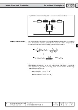
with voltage stabilization
without voltage stabilization
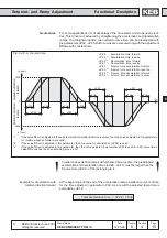
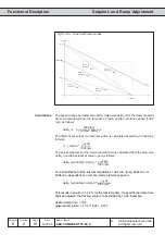
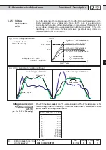
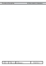
Fig. 6.5.5.b Example: Acceleration with load
Load
Load
Motor voltage
Motor speed
Motor voltage
Motord speed
U
A
bei U
N
= 250V unstabilized
U
A
bei U
N
= 190V unstablized
U
A
bei U
N
= 190V stablized
U
A
bei U
N
= 250V stabilized
Example: uF.9 = 230V
no Boost is adjusted
U
N
= Mains voltage
U
A
= Output voltage
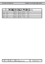
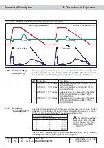
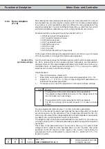
Voltage stabilization
PT1-time constant
(uF.19)
(only for F5-G >= D-housing)
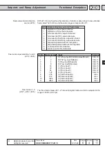
With uF.19 the time constant of a PT1-element is defined. The PT1-element serves for
the smoothing of the DC-link voltage. The initial value of the PT1-element is used as
actual value for the voltage stabilization.
uF.19
PT1-time constant
0
Function off
1
2 ms
2
4 ms
3
8 ms
4
16 ms
5
32 ms
6
64 ms
7
128 ms
8
256 ms
9
512 ms
10
1024 ms