


6
6
KEB COMBIVERT F5-M / S
4
Name: Basis
12.05.04
Chapter
Section
Page
Date
©
KEB Antriebstechnik, 2002
All Rights reserved
Functional Desription
Motor Data and Controller
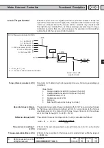
Ohm
U
V
W
PE
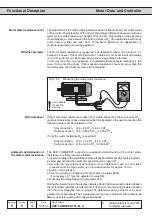
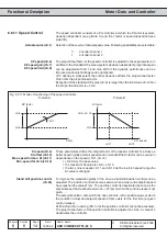
Motor stator resistance (dr.6)
The adjustment of the motor stator resistance has an influence that is not unimportant
on the control characteristics of the drive. Temperature differences between cold and
warm motors entail resistance changes of up to 40%. Depending on the operating
characteristics a value between the cold resistance R
20
(for applications with many
down times e.g. lifts) and max. 80 % of the warm resistance (for applications in
continuous operation) should be adjusted.
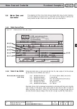
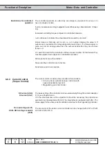
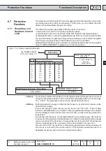
The motor stator resistance is measured, indenpendent of the motor wiring (
∆
/ Y),
between 2 phases of the motor feed cable. To obtain a more exact result all 3 values
(U/V, U/W and V/W) can be measured and the average value be formed.
In this way the ohmic line resistance is registered simultaneously (important in the
case of long incoming lines). If the measured resistance should be larger than the
maximal value, the maximal value is to be adjusted.
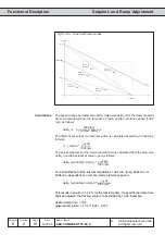
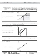
Fig. 6.6.2
Measuring the motor stator resistance
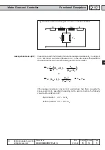
With the ohmmeter
If the motor stator resistance is taken from a data sheet, then there is usually R1
20
-
equivalent resistance (phase value) specified. Depending on the used connection the
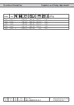
following value must be adjusted in dr.6:
Star connection:
dr.6 = 2 è R1
20
to 2,24 è R1
20
Delta connection: dr.6 = 0,666 è R1
20
to 0,75 è R1
20
If only the warm resistance R
W
is specified:
Star connection:
dr.6 = 1,4 è R1
W
to 1,6 è R1
W
Delta connection: dr.6 = 0,46 è R1
W
to 0,53 è R1
W
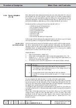
Automatic determination of
the motor stator resistance
The KEB COMBIVERT supports an automatic determination of the motor stator
resistance. For that proceed as follows:
è input motor data of the identification plate into the parameter set which is to programm.
è select and activate the parameter set which is to programm.
è Execute the measurement deoendent on the operational case in cold status
respectively let the motor warm up in no-load operation for approx. 10 min.
è Switch control release
è Preset no direction of rotation (inverter must be in status ÑLSì)
- if necessary oP.1 must be adjusted to value Ñ6ì -
è Write maximal value Ñ50000ì to parameter dr.6
During the determination the display indicates Ñcddì. Upon successful determination
the motor stator resistance is entered in dr.6. If an error occurs during the determination
then the error signal ÑE.cddì is output. The detection can be carried out for each
parameter set separately. Thus a parameter set can be programmed for example as
ÑWarm-up setì for particularly critical applications.
With data sheet
Use suitable
measuring
devices