


6
6
11
3
KEB COMBIVERT F5-M / S
Name: Basis
06.05.04
Section
Page
Date
©
KEB Antriebstechnik, 2002
All Rights reserved
Chapter
Functional Desription
Positioning and Synchronous Control
6.11 Positioning and
Synchronous
Control
6.11.1 Synchronous
Control
A synchronization and a positioning module is integrated in the KEB COMBIVERT
F5-M / S. In this modes the defined inputs in PS.1, PS.13, PS.29, PS.36 and PS.37
are scanned with a rising edge and a scan time of 250 µs.
The synchronous module realizes a multi-motor synchronous control. Several motors
can be operated angular-synchronous to a master drive (control drive). The speed
relations are individually adjustable. The control drive must not be controlled. The
synchronous module can only be activated when the inverter is equipped with a se-
cond incremental encoder input.
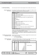
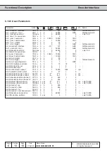
With PS.0 bit 0...2 the synchronous run respectively the positioning operation is selected.
PS.0
Posi/Synchron Mode
Bit 0...2 Activation of Posi or Synchron mode
0
Off; Posi or Synchron mode switched off; position stanstill controller
(PS.6) not active. The drive runs controlled, speed- or torque-controlled
(dependent on SC.0).
1
Synchronous mode
2..4
reserved (off)
5
Posi mode
6
Contouring mode
7
Activation by control word
Bit 3...9 Posi mode
for Posi module only (see chapter 6.11.7)
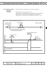
Bit 10
Start synchronous with ramp (oP.28)
0
The synchronizing after Start Synchronous does not take place with the
ramp from oP.28. The start offset (PS.5) defines the increments of the
master, after which master and slave shall run synchronously.
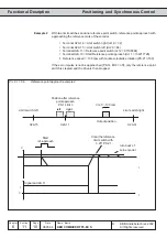
1024
The synchronizing after Start Synchronous takes place according to the
ramp from oP.28. Here PS.5 is the offset from the start input to the
position of the slave. If the start input lies, for example, left to the position
of the slave, a positive offset must be preset.
Further adjustment possibilities of PS.0 for Posi-module only (see Chapter 6.11.7)
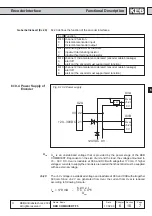
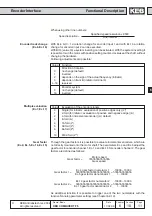
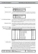
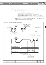
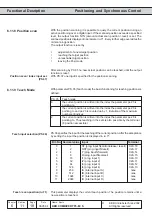
The synchronous control can be activated by way of a programmable input. By activating
the synchronous run the master position is set equal to the slave position. The input is
determined with PS.2:
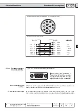
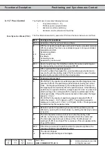
Posi-/Synchron mode (PS.0)
Posi-/Synchron input
selection (PS.2)
Bit -No. Decimal value
Input
Terminal
0
1
ST (prog. input Ñcontrol release / resetì)
X2A.16
1
2
RST (prog. input Ñresetì)
X2A.17
2
4
F (prog. input Ñforwardì)
X2A.14
3
8
R (prog. input Ñreverseì)
X2A.15
4
16
I1 (prog. input 1)
X2A.10
5
32
I2 (prog. input 2)
X2A.11
6
64
I3 (prog. input 3)
X2A.12
7
128
I4 (prog. input 4)
X2A.13
8
256
IA (internal input A)
none
9
512
IB (internal input B)
none
10
1024
IC (internal input C)
none
11
2048
ID (internal input D)
none