


11
2
1
11
KEB COMBIVERT F5
Name: Basis
04.05.04
2
©
KEB Antriebstechnik, 2002
All Rights reserved
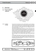
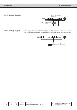
Product Description
Summary
Section
Page
Date
Chapter
25
26
27
U
U
U
3
3
3
[kVA]
145
173
208
[kW]
110
132
160
[A]
210
250
300
[A]
263
313
375
[A]
315
375
450
[A]
231
275
330
[A]
315
400
450
[kHz]
4
4
2
[kHz]
8
8
8
[W]
2300
2800
3100
[A]
210
250
240
-
[
∞
C]
90
[mm
≤
]
95
120
150
[Ohm]
4
4
4
[Ohm]
4,3
4,3
4,3
[A]
200
200
200
2
[Nm]
25
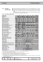
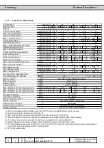
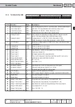
Inverter Size
Housing size
Phases
Output nominal power
Max. rated motor power
Output nominal current
Max. short time current
1)
OC-tripping current
Nominal input current
Max. permissible mains fuse (inert)
Rated switching frequency
Max. switching frequency
Power loss at nominal operating
Stall current at 4kHz
2)
Stall current at 8kHz
2)
Stall current at 16kHz
2)
Max. heat sink temperature TOH
Motor line cross section
3)
Min. braking resistor
4)
Typ. braking resistor
4)
Max. braking current
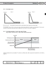
Overload curve (page appendex)
Tightening torque for terminals
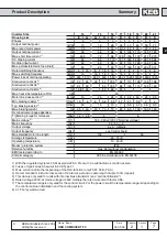
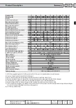
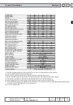
Mains voltage
5)
Mains frequency
Output voltage
Output frequency
Max. shielded motor line length
Storage temperature
Operating temperature
Model / protective system
Relative humidity
EMC tested according to
Climatic category
[V]
305...500 ±0 (400 V Nominal voltage)
[Hz]
50 / 60 +/- 2
[V]
3 x 0...U Mains
[Hz]
see Control board
[m]
50
[
∞
C]
-25...70
∞
C
[
∞
C]
-10...40
∞
C
IP20
max. 95% without condensation
EN 61800-3
3K3 in accordance with EN 50178
1) With the regulated systems F5-M as well as F5-S 5% are to be subtracted as control reserve.
2) Fuses of type Ferraz Shawmut 6,6 UD Type 31
3) Max. current before the responding of the OL2-function (only F5-M; F5-S; F5-A)
4) Recommended minimum cross section for rated power and a cable length of upto 100m (copper)
5) This data is only valid for units with internal brake transistor (see "unit identification")
6) Rated voltage 400V; at mains voltage
≥
460V multiply the rated current with factor 0.86.
7) The temperature range is only valid for the control circuit. For the power circuit the temperature range is depending on
the control cabinet installation and the cooling system.
8) 31.F5 only watercooled.