


19
6
7
19
KEB COMBIVERT F5
Name: Basis
04.05.04
6
Abschnitt
Seite
Datum
©
KEB Antriebstechnik, 2002
All rights reserved
Kapitel
Functional Description
Protective Functions
6.7.9
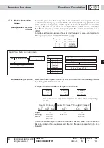
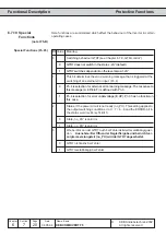
GTR7-Control
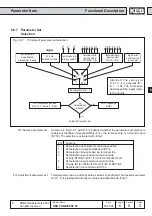
The GTR7 (brake transistor) serves for the control of the brake resistor.
As a standard the GTR7 is switched in dependence on the DC-link voltage, in order to
discharge fed-back energy. The switching behaviour of the GTR7 can be altered with
the parameters Pn.64 and Pn.65. In the following some applications are specified, at
which the factory setting should be modified.
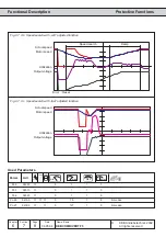
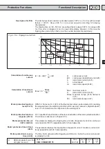
Output filters, with the contained capacities and inductivities, form an oscillatory circuit
with the motor, thus the drive also operates as generator.
Synchronous motors operate as generator even if the modulation is switched off. .
Especially at low-load systems voltages can be induced, which can lead to the
destruction of the inverter if no attention is paid to it.
The energy fed into the intermediate circuit is transferred over the GTR7 to the brake
resistor. However, as a standard the GTR7 only operates if the inverter modulates.
Generally drives should always be decelerated in a controlled manner.
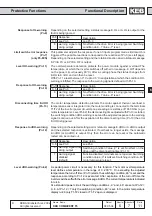
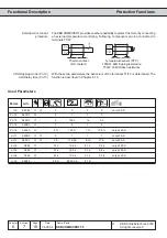
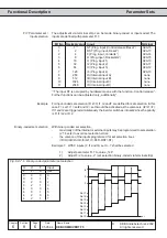
With parameter Pn.65 the switching behaviour of the GTR7 can be adjusted as follows:
Pn.65 Switching behaviour GTR7
0
not in status „LS“ (default)
1
also switches at „LS“
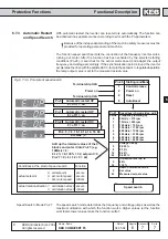
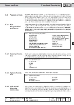
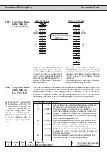
With Pn.64 an input can be defined for the activation of the GTR7. In this case the
GTR7 switches independent of the inverter status and the DC-link voltage as soon as
the input is active.
Exception: On opening the control release (noP) the inverter must switch off the GTR7
for safety reasons.
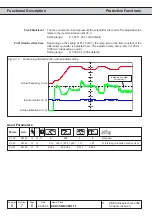
Output filter
Parallel connnection of
inverters (DC-
interconnection)
Input selection GTR7 (Pn.64)
Special functions (Pn.65 Bit 0)
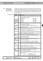
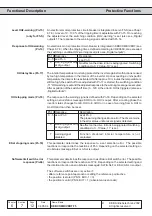
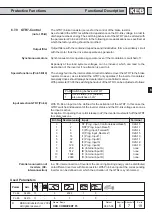
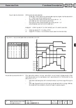
In a DC-interconnection of inverters the occurring braking energy can be distributed
onto different inverters with brake resistor. With Pn.64 an input at the corresponding
inverter can be defined over which the activation of the GTRs is synchronized.
Bit -No. Decimal value Input
Terminal
0
1
ST (Prog. input „Control release/Reset“)
X2A.16
1
2
RST (Prog. input „Reset“)
X2A.17
2
4
F (Prog. input „Forward“)
X2A.14
3
8
R (Prog. Input „Reverse“)
X2A.15
4
16
I1 (Prog. Input 1)
X2A.10
5
32
I2 (Prog. Input 2)
X2A.11
6
64
I3 (Prog. input 3)
X2A.12
7
128
I4 (Prog. input 4)
X2A.13
8
256
IA (Internal input A)
none
9
512
IB (Internal input B)
none
10
1024
IC (Internal input C)
none
11
2048
ID (Internal input D)
none
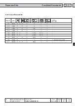
Param.
Adr.
min
max
default
ENTER
PROG.
R/W
Step
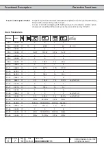
Used Parameters
Pn.64
0440h
✔
-
-
0
4095
1
0
-
Pn.65
0441h
✔
-
-
0
7
1
0
-
Synchronous motors
(not at F5-B)