


6
3
KEB COMBIVERT F5
16
Name: Basis
28.01.03
Chapter
Section
Page
Date
©
KEB Antriebstechnik, 2002
All rights reserved
Functional Description
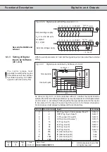
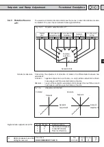
Digital In- and Outputs
&
>1
0
1
Bit 0
8
do.16
&
>1
0
1
Bit 1
8
do.17
&
>1
0
1
Bit 7
8
do.23
do.24
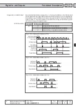
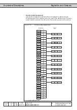
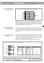
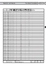
Fig. 6.3.15
Inversion and selection of switching conditions
6.3.16 Inverting of Switching
Conditions for Flags
(do.8...do.15)
With the parameters do.8...do.15 each of the 8 switching conditions (do.0...do.7)
can be inverted for each flag separately. Through this function it is possible to set
any chosen switching condition as Non-condition. The parameter is bit-coded.
According to Fig. 6.3.15 the weighting of the switching conditions to be inverted
must be entered in do.8...do.15. If several conditions shall be inverted, the sum is
to be formed.
Output X2A.19 shall be set when the inverter is not accelerating. In this case we
assign the switching condition 21 (inverter accelerates) for example to do.1 (enter
value 21). We invert the switching condition with do.9, so enter value 2.
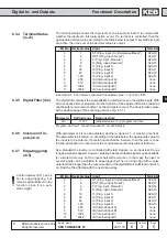
6.3.17 Selection of
Switching
Conditions for Flags
(do.16...do.23)
Example:
The parameters do.16...do.23 serve for the selection of the 8 defined switching
conditions. The selection is done for each chanel separately, where one can choose
between no one and up to all 8 switching conditions. According to Fig. 6.3.15 the
weighting of the selected switching conditions is to be entered into do.16...do.23 . If
several conditons are selected, the sum is to be formed.
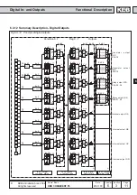
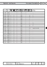
After the switching conditons are selected for each output, it can now be determined,
how these are linked. As a default all conditions are OR-operated, i.e. if one of the
selected conditions is met, the output switches. Another possibility is the AND-
operation which can be adjusted with do.24. AND-operation means that all selected
conditions must be fulfilled before the output switches.
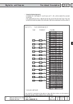
Parameter do.24 is bit-coded. The table under 6.3.17 shows the assignment.
6.3.18 Linking the
Switching
Conditions for Flags
(do.24)
Fig. 6.3.17
Linking the switching conditions in logic step 1
8
do.24
1
1
1
1
do.8...do.15
do.0
do.1
do.2
do.3
do.4
do.5
do.6
do.7
1
2
4
8
16
32
64
128
do.16...do.23
1
2
4
8
16
32
64
128
1
1
1
1
Flag 0
Flag 1
Flag 7