


6
6
1
11
KEB COMBIVERT F5-M / S
Name: Basis
12.05.04
Section
Page
Date
©
KEB Antriebstechnik, 2002
All Rights reserved
Chapter
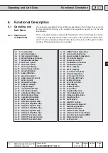
Functional Desription
Operating and Unit Data
Adr.
min
max
default
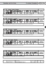
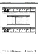
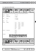
0217h
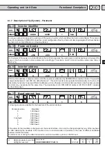
ru.23
Output condition state
1
-
-
255
0
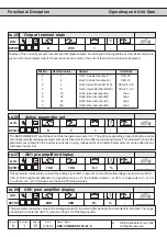
With parameters do.0Ödo.7 switching conditions can be selected which serve as basis for the setting of the outputs.
This parameter indicates which of the selected switching conditions are met, before they are linked by the programmable
logic or inverted (see Chapter 6.3 ÑDigital Outputs). According to following table a certain decimal value is given out for
the parameters do.0Ödo.7. If several of the switching conditions selected with these parameters are met, then the sum
of the decimal values is displayed.
Bit -No.
Decimal value
Output
0
1
switching condition 0 (do.0)
1
2
switching condition 1 (do.1)
2
4
switching condition 2 (do.2)
3
8
switching condition 3 (do.3)
4
16
switching condition 4 (do.4)
5
32
switching condition 5 (do.5)
6
64
switching condition 6 (do.6)
7
128
switching condition 7 (do.7)
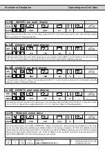
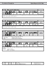
Adr.
min
max
default
0217h
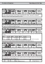
ru.24
State of output flags
1
-
-
255
0
Display of the links after logic step 1. The selected switching conditions are linked in logic step 1 (do.8...24) and
indicated here (see Chapt. 6.3 ÑDigital outputsì). According to following table a specific decimal value is given out for
each linkage. If several links are set, the sum of the decimal values is indicated.
Bit -No.
Decimal value
Output
0
1
flag 0
1
2
flag 1
2
4
flag 2
3
8
flag 3
4
16
flag 4
5
32
flag 5
6
64
flag 6
7
128
flag 7