


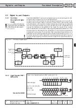
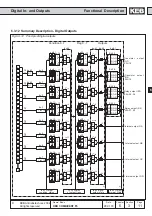

6
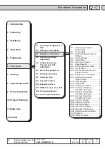
Functional Description
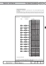
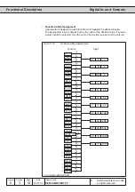
Analog In- and Outputs
6
2
13
KEB COMBIVERT F5
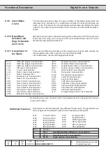
Name: Basis
Chapter Section
Page
Date
©
KEB Antriebstechnik, 2002
All rights reserved
04.05.04
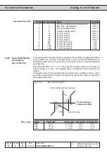
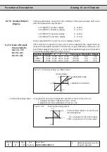
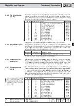
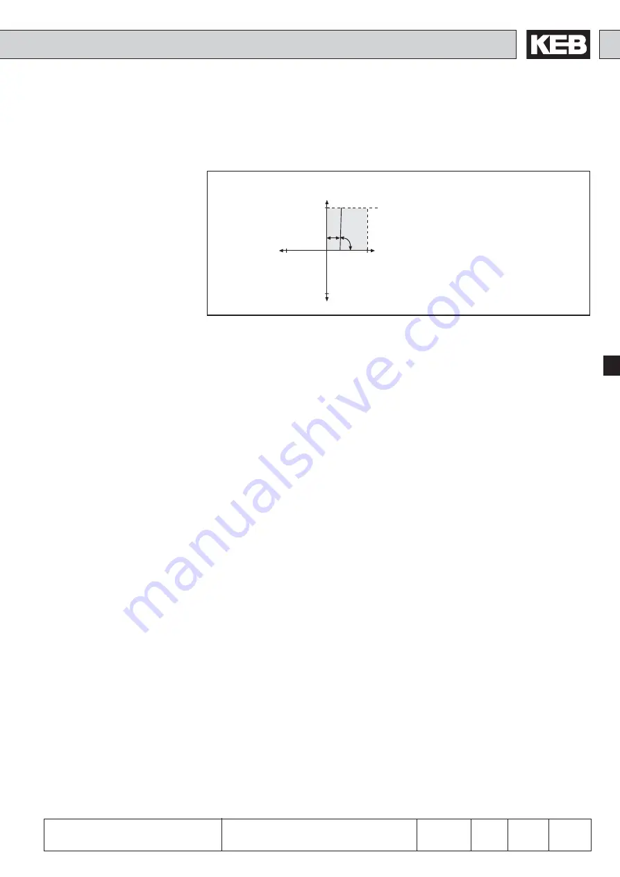
Since the analog output always works firmly onto the values defined under 6.2.10, one
can adjust the characteristic with the aid of the amplification so that the complete
range of 0...±10V is utilized.
defined value
ñññññññññññ = Amplification (An.33 / 38 / 43 / 49)
desired value
Example output frequency
100Hz
ñññññ = 1,47
68Hz
Computation of the amplification
10V
100%
-100%
-100%
An.34
100%
An.33
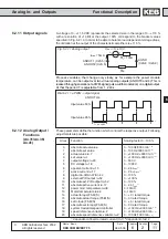
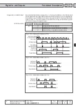
Because of the high amplification the
analog output switches in a relative small
switching window.
Analog output as switch
An example for using the analog output as 0/10V-switch is shown in Fig. 6.2.14.c:
1. adjustment of the amplification (An.33) to 20.00
2. adjustment of the X-Offset (An.34) to the desired switching level
Fig. 6.2.14.c
Analog output as switch
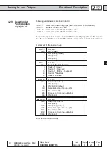
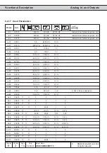
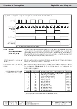
6.2.15 Period ANOUT3
(An.46)
The amount of the selected process variable (An.41/47) is converted into a percentage.
The output of the characteristic amplifier (An.43...45 / An.49...51) is limited to values
from 0...100†%. The multiplication of the base value with the cycle duration (An.46 /
52) results in the ON period of the digital output (selection in do.0..7 value Ñ42/43ì).
The period can be adjusted in a range from 1...240 s.
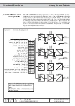
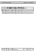
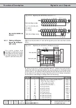
6.2.16 ANOUT 1...4
Digital Settings
(An.32/37/42/48)
With these parameters analog values can be adjusted in percent for the respective
input. For that purpose the value Ñ8 digital settingì must be adjusted as process vari-
able. The setting is done within the range ±100 %.