


XC2200 Derivatives
System Units (Vol. 1 of 2)
System Control Unit (SCU)
User’s Manual
6-91
V2.1, 2008-08
SCU, V1.13
6.5.2.1
PVC Status and Control Registers
These registers are the software interface for PVC_1 and PVC_M.
The registers are updated by the PSC.
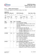
PVC1CON0
PVC_1 Control Step 0 Register
ESFR (F014
H
/0A
H
)
Reset Value: 0504
H
15
14
13
12
11
10
9
8
7
6
5
4
3
2
1
0
L2
AS
EN
L2
RST
EN
L2
INT
EN
L2
A
LEV
LEV
2
OK
LEV2V
L1
AS
EN
L1
RST
EN
L1
INT
EN
L1
A
LEV
LEV
1
OK
LEV1V
rwh rwh rwh rwh
rh
rwh
rwh rwh rrwh rwh
rh
rwh
Field
Bits
Type
Description
LEV1V
[2:0]
rwh
Level Threshold 1 Voltage
This bit field defines the Level Threshold 1 that is
compared with the DMP_1 core voltage.
The values for the different configurations are listed
in the data sheet.
LEV1OK
3
rh
Level Threshold 1 Check Result
0
B
The core supply voltage of the DMP_1 is below
Level Threshold 1 voltage LEV1V
1
B
The core supply voltage of the DMP_1 is equal
or above the Level Threshold 1 voltage LEV1V
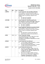
L1ALEV
4
rwh
Level Threshold 1 Action Level
0
B
When the core supply voltage is below Level
Threshold 1 voltage LEV1V the action
configured by bits L1INTEN, L1RSTEN, and
L1ASEN are requested
1
B
When the core supply voltage is equal or
above Level Threshold 1 voltage LEV1V the
actions configured by bits L1INTEN,
L1RSTEN, and L1ASEN are requested


