


XC2200 Derivatives
System Units (Vol. 1 of 2)
System Control Unit (SCU)
User’s Manual
6-25
V2.1, 2008-08
SCU, V1.13
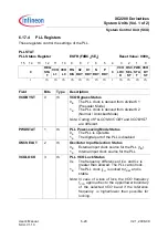
GAINSEL
[5:4]
r
Oscillator Gain Selection
00
B
Reserved
01
B
Reserved
10
B
Reserved
11
B
The gain control is configured for frequencies
from 4 MHz to 25 MHz
Note: Used for testing only.
X1D
6
rh
XTAL1 Data Value
This bit reflects the inverted level of pin XTAL1.
This bit is sampled with
f
SYS
while X1DEN is set.
Note: Voltages on XTAL1 must comply to the voltage
defined in the data sheet.
X1DEN
7
rw
XTAL1 Data Enable
0
B
Bit X1D is not updated
1
B
Bit X1D can be updated
SHBY
8
rw
Shaper Bypass
The shaper forms a proper signal from the input
signal. This bit must be 0 for proper operation.
0
B
The shaper is not bypassed
1
B
The shaper is bypassed
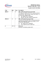
EMCLKEN
9
rw
OSCWDT Emergency System Clock Source
Select Enable
This bit requests the master clock multiplexer (MCM)
to switch to an alternate clock (selected by bit field
SYSCON0.EMCLKSEL) in an OSCWDT emergency
case.
0
B
MCM remains controlled by
SYSCON0.CLKSEL
1
B
MCM is controlled by SYSCON0.EMCLKSEL
EMFINDISEN
10
rw
Emergency Input Clock Disconnect Enable
This bit defines if bit PLLSTAT.FINDIS is set in an
OSCWDT emergency case.
0
B
No action
1
B
PLLSTAT.FINDIS is set in an emergency case
Note: Please refer to the Programmer’s Guide for a
description of the proper handling.
Field
Bits
Type
Description


