


XC2200 Derivatives
System Units (Vol. 1 of 2)
System Control Unit (SCU)
User’s Manual
6-11
V2.1, 2008-08
SCU, V1.13
sporadic clock pulses coming from the oscillator circuit. Without a clock input
f
R
, the PLL
gradually slows down to its VCO base frequency and remains there. The automatic
disconnection of the VCO from its input clock
f
R
in case of a VCO Loss-of-Lock event
can be enabled by setting bit PLLCON1.EMFINDISEN. If this bit is cleared the clock
f
R
remains connected to the VCO.
Configuration and Operation of the Prescaler Mode
In Prescaler Mode, the PLL is running at frequency
f
PLL
, where
f
R
is divided by the K1-
Divider.
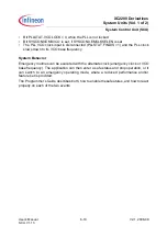
Figure 6-8
PLL Prescaler Mode Diagram
The Prescaler Mode is selected by the following setting:
•
PLLCON0.VCOBY = 1
The Prescaler Mode is entered when all following conditions are true:
•
PLLSTAT.VCOBYST = 0
•
HPOSCCON.PLLV = 1
Operation in Prescaler Mode requires an input clock frequency
f
R
. If
f
IN
is selected as
clock source for
f
R
it is recommended to check and monitor if an input frequency
f
OSC
is
available at all by checking HPOSCCON.PLLV. There are no requirements regarding the
frequency of
f
R
.
The system operation frequency in Prescaler Mode is controlled by the value of the K1-
Divider. When the value of PLLCON1.K1DIV was changed the next update of this value
should not be done before bit PLLSTAT.K1RDY is set.
PLL _Prescaler _Mode.vsd
PLL Block
f
IN
Osc.
WDG
K1-
Divider
f
PLL
f
K1
f
R
PLLCON 1.
OSCSEL
PLLCON0.
VCOBY
M
U
X
M
U
X
1
0
0
1
Clock
Source
f
INT
HPOSCCON.
PLLV
HPOSCCON.
OSCWDTRST


