


XC2200 Derivatives
System Units (Vol. 1 of 2)
System Control Unit (SCU)
User’s Manual
6-38
V2.1, 2008-08
SCU, V1.13
6.1.7.5
System Clock Control Registers
These registers control the system level clock behavior.
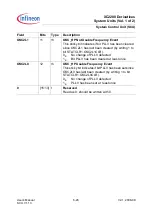
SYSCON0
System Control 0 Register
SFR (FF4A
H
/A5
H
)
Reset Value: 0000
H
15
14
13
12
11
10
9
8
7
6
5
4
3
2
1
0
SEL
STA
T
0
EMS
VCO
EMS
OSC
0
EM
CLK
SEL
EN
0
EM
CLKSEL
0
CLKSEL
rh
r
rh
rh
r
rw
r
rw
r
rw
Field
Bits
Type
Description
CLKSEL
[1:0]
rw
Clock Select
This bit field defines the clock source that is used as
system clock for normal operation.
00
B
The Wake-up clock
f
WU
is used
01
B
The oscillator clock (OSC_HP)
f
OSC
is used
10
B
The PLL clock
f
PLL
is used
11
B
CLKIN1 as direct input clock
f
CLKIN1
is used
EMCLKSEL
[4:3]
rw
Emergency Clock Select
This bit field defines the clock source that is used as
system clock in case of an OSCWDT or VCOLCK
emergency event.
00
B
The Wake-up clock
f
WU
is used
01
B
The oscillator clock (OSC_HP)
f
OSC
is used
10
B
The PLL clock
f
PLL
is used
11
B
CLKIN1 as direct input clock
f
CLKIN1
is used
EMCLKSELEN
6
rw
Emergency Clock Select Enable
Controls switching the system clock to an alternate
source in case of an OSCWDT or VCOLCK event.
0
B
The switching is disabled
1
B
The switching is enabled
EMSOSC
12
rh
OSCWDT Emergency Event Source Status
0
B
No OSCWDT emergency event occurred since
EMSOSC has been cleared last
1
B
An OSCWDT emergency event has occurred
Note: This bit is only set if EMCLKSELEN is set.


