


XC2200 Derivatives
System Units (Vol. 1 of 2)
System Control Unit (SCU)
User’s Manual
6-41
V2.1, 2008-08
SCU, V1.13
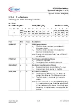
6.1.7.6
RTC Clock Control Register
Note: Only change register RTCCLKCON while the RTC is off.
RTCCLKCON
RTC Clock Control Register
SFR (FF4E
H
/A7
H
)
Reset Value: 0006
H
15
14
13
12
11
10
9
8
7
6
5
4
3
2
1
0
0
RTC
CM
RTC
CLKSEL
r
rw
rw
Field
Bits
Type
Description
RTCCLKSEL
[1:0]
rw
RTC Clock Select
This bit field defines the count clock source for the
RTC.
00
B
The PLL clock
f
PLL
is used
01
B
The oscillator clock (OSC_HP)
f
OSC
is used
10
B
The Wake-up clock signal
f
WU
is used
11
B
CLKIN2 as direct input clock
f
CLKIN2
is used
RTCCM
2
rw
RTC Clocking Mode
0
B
Asynchronous Mode:
The RTC internally operates with
f
RTC
.
No register access is possible.
1
B
Synchronous Mode:
The RTC internally operates with
f
SYS
clock.
Registers can be read and written.
0
[15:3]
r
Reserved
Read as 0; should be written with 0.


