


XC2200 Derivatives
System Units (Vol. 1 of 2)
System Control Unit (SCU)
User’s Manual
6-9
V2.1, 2008-08
SCU, V1.13
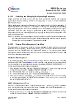
Figure 6-7
PLL Normal Mode Diagram
The Normal Mode is selected by the following settings:
•
PLLCON0.VCOBY = 0
•
STATCLR1.CLRFINDIS = 1
The Normal Mode is entered when all following conditions are true:
•
PLLSTAT.FINDIS = 0
•
PLLSTAT.VCOBYST = 1
•
PLLSTAT.VCOLOCK = 1
•
HPOSCCON.PLLV = 1
Operation in Normal Mode requires a clock frequency of
f
R
. When
f
IN
is selected as
source for
f
R
it is recommended to check and monitor if an input frequency
f
R
is available
at all by checking HPOSCCON.PLLV.
The system operation frequency in Normal Mode is controlled by the values of the three
dividers: P, N, and K2. A modification of the two dividers P and N has a direct influence
on the VCO frequency and leads to a loss of the VCO Lock status. A modification of the
K2-divider has no impact on the VCO Lock status but changes the PLL output frequency.
Note: Changing the system operation frequency by changing the value of the K2-Divider
has a direct influence on the power consumption of the device. Therefore, this has
to be done carefully.
To modify or enter the Normal Mode frequency, follow the sequence described below:
Configure and enter Prescaler Mode. For more details see the Prescaler Mode.
Disable the trap generation for the VCO Lost-of-Lock.
PLL _Normal_Mode.vsd
PLL Block
f
IN
Osc.
WDG
P-
Divider
VCO
Core
K2-
Divider
N-
Divider
Lock
Detect.
f
PLL
f
K2
f
VCO
f
DIV
f
REF
f
P
f
R
PLLCON 1.
OSCSEL
PLLSTAT .
FINDIS
PLLCON0.
VCOBY
M
U
X
M
U
X
1
0
0
1
Clock
Source
f
INT
PLLSTAT .
VCOLOCK
HPOSCCON.
PLLV
PLLCON1.
RESLD
HPOSCCON.
OSCWDTRST


