


XC2200 Derivatives
System Units (Vol. 1 of 2)
System Control Unit (SCU)
User’s Manual
6-79
V2.1, 2008-08
SCU, V1.13
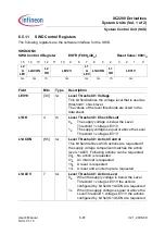
ESR Configuration Register
The ESR configuration registers contains bits required for the behavioral control of the
ESR pins.
ESRCFG0
ESR0 Configuration Register
ESFR (F100
H
/80
H
)
Reset Value: 000E
H
ESRCFG1
ESR1 Configuration Register
ESFR (F102
H
/81
H
)
Reset Value: 0002
H
ESRCFG2
ESR2 Configuration Register
ESFR (F104
H
/82
H
)
Reset Value: 0002
H
15
14
13
12
11
10
9
8
7
6
5
4
3
2
1
0
0
AEDCON SEDCON
IN
OUT
DF
EN
PC
r
rw
rw
rh
rh
rw
rw
Field
Bits
Type
Description
PC
[3:0]
rw
Pin Control of ESRx
This bit field controls the behavior of the associated
ESRx pin.
The coding is described in
DFEN
4
rw
Digital Filter Enable
This bit defines if the 3-stage median filter of the
ESRx is used or bypassed.
0
B
The filter is bypassed
1
B
The filter is used
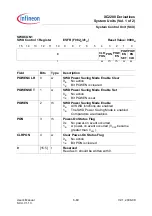
OUT
5
rh
Data Output
This bit can be used as output value for the
associated ESRx pin.
0
B
If selected, the output level is 0
1
B
If selected, the output level is 1
This bit is controlled via bit field ESRDAT.MOUTx.
IN
6
rh
Data Input
This bit monitors the input value at the associated
ESRx pin.


