3.1 Overview
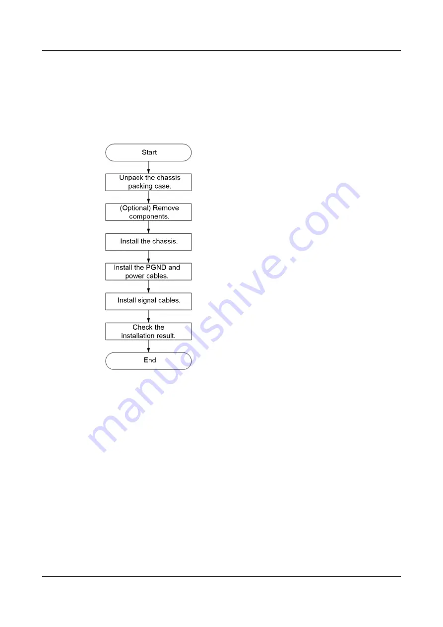
Installation Process
Figure 3-1
Installation process
Prerequisites
Documents
l
Chassis layout diagram (included in the product documentation bag), which shows
the
position for installing a chassis in the cabinet
.
l
Component layout diagram (included in the product documentation bag), which shows
the positions for installing compute nodes and switch modules in the E9000 chassis
.
l
Cable routing table (provided by onsite delivery personnel), which shows
the
connections for power cables and signal cables
.
Tools
l
Protective gloves
l
ESD gloves
l
Diagonal pliers
l
Box cutter
l
Phillips screwdriver (PH3 is 8 mm or 0.31 in.)
E9000 Server
User Guide
3 Installing the E9000
Issue 25 (2019-11-30)
Copyright © Huawei Technologies Co., Ltd.
45


