2-4
745 Transformer Management Relay
GE Power Management
2.2 CHANGING SETPOINTS
2 GETTING STARTED
2
2.2.4 ENUMERATION SETPOINTS
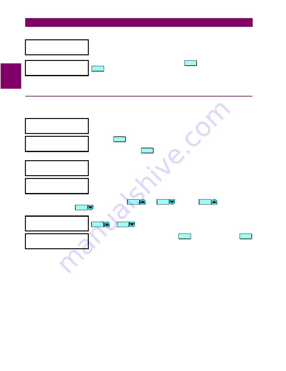
Enumeration setpoints have data values which are part of a set, whose members are explicitly defined by a
name. A set is comprised of two or more members.
Enumeration type values are changed using the
and
keys. The
key displays the
next selection while the
key displays the previous selection.
NOMINAL VT SECONDARY
VOLTAGE
As an example, let’s set the nominal VT secondary voltage setpoint to 69.3 V.
Press the appropriate numeric keys in the sequence ‘6 9 . 3‘. The display
message will change as the digits are being entered.
yy
NEW SETPOINT
yy
HAS BEEN STORED
Editing changes are not registered until the
key is pressed. Press the
key to store the new value in memory. This flash message momentarily
appears to confirmation the storing process. If 69.28 were entered, the value is
automatically rounded to 69.3, since the step value for this setpoint is 0.1.
PHASE SEQUENCE
ABC
Move to message
S2 SYSTEM SETUP / TRANSFORMER / PHASE SEQUENCE
.
yy
PRESS [VALUE
Ú
Ú
] TO
yy
MAKE SELECTION
Press the
key and the following context sensitive flash messages will
sequentially appear for several seconds each. For the case of an enumeration
setpoint message, the
key displays the number of selections in the
enumeration.
yy
PRESS [ENTER]
TO
yy
STORE NEW VALUE
yy
FOR FURTHER HELP
yy
REFER TO MANUAL
INPUT 1 FUNCTION:
ENABLED
As an example we may need to set the phase sequence to ACB. Press
or
until the proper selection is displayed.
yy
NEW SETPOINT
yy
HAS BEEN STORED
Editing changes are not registered until
is pressed. Pressing
stores the new value in memory. This flash message momentarily appears to
confirm the storing process.
E N TE R
E N TE R
H E LP
H E LP
V AL U E
V AL U E
V AL U E
V A LU E
V AL U E
V AL U E
E N TE R
E N TE R
Summary of Contents for 745 TRANSFORMER MANAGEMENT RELAY
Page 30: ...2 8 745 Transformer Management Relay GE Power Management 2 3 SECURITY 2 GETTING STARTED 2 ...
Page 210: ...7 36 745 Transformer Management Relay GE Power Management 7 2 BLOCK DIAGRAMS 7 SCHEME LOGIC 7 ...
Page 322: ...9 12 745 Transformer Management Relay GE Power Management 9 3 USING 745PC 9 745 PC SOFTWARE 9 ...
Page 396: ...A 4 745 Transformer Management Relay GE Power Management A 1 FIGURES AND TABLES APPENDIXA A ...
Page 400: ...C 2 745 Transformer Management Relay GE Power Management C 1 WARRANTY INFORMATION APPENDIXC C ...
Page 406: ...vi 745 Transformer Management Relay GE Power Management ...
Page 407: ...GE Power Management 745 Transformer Management Relay NOTES ...


