9-6
745 Transformer Management Relay
GE Power Management
9.2 INSTALLATION & CONFIGURATION
9 745 PC SOFTWARE
9
9.2.2 STARTUP & COMMUNICATIONS CONFIGURATION
Startup of the 745PC software is accomplished as follows:
1.
Double-click on the 745 program icon inside the GE Power Management group or select from the Win-
dows Start menu to launch 745PC. The 745 to PC communications status is displayed on the bottom right
corner of the screen:
2.
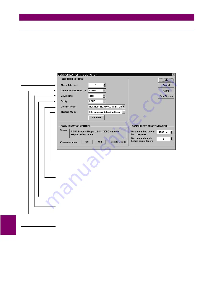
To configure communications, select the Communication > Computer menu item. The COMMUNICA-
TION / COMPUTER dialog box will appear containing the various communications settings for the local
PC. These settings should be modified as shown below:
Figure 9–7: COMMUNICATION/COMPUTER DIALOG BOX
3.
To begin communications, click on the ON button in the in the Communication section of the dialog box.
The Status section indicates the communication status. If communications is established, the message
“Program is now talking to a Multilin device” is displayed. As well, the status at the bottom right hand corner
of the screen indicates “Communicating”.
S et the
based on user pre feren ce. In “Com m unicate w ith R elay” m ode, 745PC will attem pt
to establish com m unica tions im m ediately upon startup. W hile in the “F ile m ode /w default settings”, 745P C
w aits for th e use r to click the O N button before attem pting com m unications – this m ode is preferre d wh en
the 745PC is being used w ithout a n attached 745 relay.
S tartup M o de
S et
to m atch the type of R S2 32/R S485 converter. If connected thro ugh th e 745 front panel
R S232 port, sele ct “No C ontrol Type”. If connected throug h a G E P ow er M a nagem ent F485 converter u nit,
select “M U LT ILIN R S 232/R S485 C O N V ERTO R ”. If connected throug h a m odem , select “M o dem ”. If a third-
party R S 23 2/R S485 converter is b eing used, select the a ppropriate control type from the availab le list based
on the m an ufacturer ’s specifications.
C ontro l Type
S et
to m atch the 745 PA R ITY setp oint (see S 1 745 S ETU P ). If connected throug h the 745 front panel
R S232 port, set to “N one”.
P arity
S et
to m atch the 745 B AU D R ATE setpoint (se e S 1 745 S E TUP ).
B aud R ate
S et
to
w here the 745 relay is connected (e.g. C O M 1
or C O M 2). O n m ost com puters, C O M 1 is used by the m ouse device and as such C O M 2 is usually
available for com m unications.
C om m uncation P ort #
the C O M po rt on your local PC
S et
to m atch the 745 S LAV E A D D RE S S setpoin t (see S 1 745 SE TU P).
S lave Add ress
Summary of Contents for 745 TRANSFORMER MANAGEMENT RELAY
Page 30: ...2 8 745 Transformer Management Relay GE Power Management 2 3 SECURITY 2 GETTING STARTED 2 ...
Page 210: ...7 36 745 Transformer Management Relay GE Power Management 7 2 BLOCK DIAGRAMS 7 SCHEME LOGIC 7 ...
Page 322: ...9 12 745 Transformer Management Relay GE Power Management 9 3 USING 745PC 9 745 PC SOFTWARE 9 ...
Page 396: ...A 4 745 Transformer Management Relay GE Power Management A 1 FIGURES AND TABLES APPENDIXA A ...
Page 400: ...C 2 745 Transformer Management Relay GE Power Management C 1 WARRANTY INFORMATION APPENDIXC C ...
Page 406: ...vi 745 Transformer Management Relay GE Power Management ...
Page 407: ...GE Power Management 745 Transformer Management Relay NOTES ...


