Setup & Operation 3. Environment and Installation
C8 Rev.13
37
3.4 Installation
The installation shall be made by qualified installation personnel and should conform to all
national and local codes.
WARNING
■
To ensure safety, a safeguard must be installed for the robot system. For details
on the safeguard, refer to the
Installation and Design Precautions
in the
Safety
chapter of the EPSON RC+ User’s Guide.
■
Install the Manipulator in a location with sufficient space so that a tool or a work
piece does not touch a wall or a safeguard when the Manipulator extends its arm
fully while holding a work piece. Installing the Manipulator at a location with
insufficient space is extremely hazardous and may result in serious bodily injury
and/or severe equipment damage to the robot system as a tool or a work piece
may collide with a wall or a safeguard.
■
Anchor the Manipulator before turning ON the power to or operating the
Manipulator. Turning ON the power to or operating the Manipulator that is not
anchored is extremely hazardous and may result in serious bodily injury and/or
severe equipment damage to the robot system as the Manipulator may fall down.
■
Before installing and operating the Manipulator, make sure that all parts of the
Manipulator are in place and have no external defects. Missing or defective parts
may cause improper operation of the Manipulator. Improper operation of the
Manipulator is extremely hazardous and may result in serious bodily injury and/or
severe equipment damage to the robot system.
CAUTION
■
The Manipulator must be installed to avoid interference with buildings, structures,
utilities, other machines and equipment that may create a trapping hazard or pinch
points.
■
Oscillation (resonance) may occur during operation depending on rigidity of the
installation table. If the oscillation occurs, improve rigidity of the table or change
the speed or acceleration and deceleration settings.
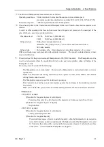
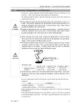
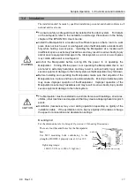
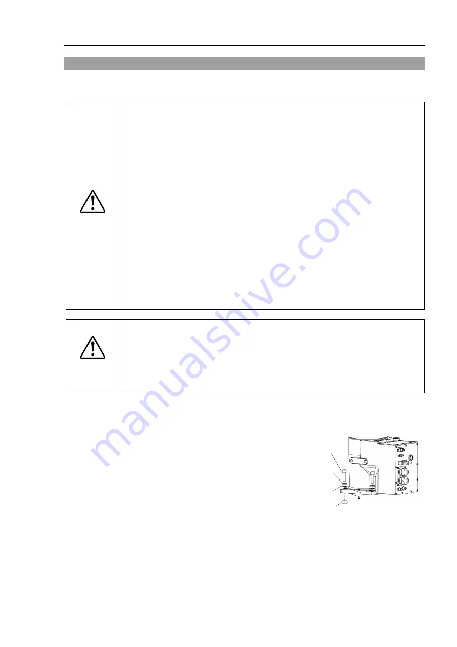
Mounting bolt
For the dimensions, refer to
Setup & Operation 3.3 Mounting Dimensions
.
There are four threaded holes for the Manipulator
base.
Use M12 mounting bolts conforming to the
strength of ISO898-1 property class 10.9 or 12.9.
Tightening torque:
100.0
±
5.0 N·m (1,020
±
51 kgf·cm)
16 mm
4-M12
×
40
Screw Hole (depth 25 mm or more)
Spring
Washer
Plane
Washer
Summary of Contents for C8 Series
Page 1: ...Rev 13 EM208R4413F 6 Axis Robots C8 series MANIPULATOR MANUAL ...
Page 2: ...Manipulator manual C8 series Rev 13 ...
Page 8: ...vi C8 Rev 13 ...
Page 14: ...Table of Contents xii C8 Rev 13 ...
Page 16: ......
Page 31: ...Setup Operation 2 Specifications C8 Rev 13 17 2 4 Outer Dimensions Unit mm 2 4 1 C8 A701 C8 ...
Page 32: ...Setup Operation 2 Specifications 18 C8 Rev 13 2 4 2 C8 A901 C8L ...
Page 33: ...Setup Operation 2 Specifications C8 Rev 13 19 2 4 3 C8 A1401 C8XL ...
Page 49: ...Setup Operation 3 Environment and Installation C8 Rev 13 35 C8 A901 C8L ...
Page 98: ......
Page 183: ...Maintenance 4 Cable Unit C8 Rev 13 169 4 2 Connector Pin Assignment 4 2 1 Signal Cable ...
Page 184: ...Maintenance 4 Cable Unit 170 C8 Rev 13 ...
Page 185: ...Maintenance 4 Cable Unit C8 Rev 13 171 ...
Page 186: ...Maintenance 4 Cable Unit 172 C8 Rev 13 4 2 2 Power Cable C8 A701 C8 C8 A901 C8L ...
Page 187: ...Maintenance 4 Cable Unit C8 Rev 13 173 C8 A1401 C8XL ...
Page 188: ...Maintenance 4 Cable Unit 174 C8 Rev 13 C8 A701 C8 C8 A901 C8L C8 A1401 C8XL ...


