


Maintenance 5. Joint #1
182
C8 Rev.13
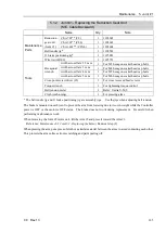
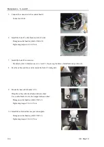
4.
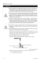
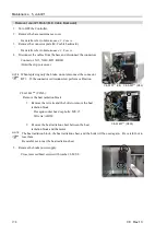
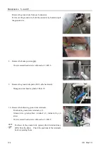
Install the Joint #1 electromagnetic brake / brake plate to the Joint 1
motor unit.
Hexagon socket head cap bolts: 3-M4
×
20
Tightening torque: 4.0
±
0.2 N·m
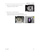
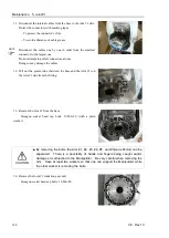
Check that the motor and the brake core are aligned.
Regarding brake misalignment:
-
Misalignment of the brake core may cause abnormal sound or
apply abnormal torque on the brake. It may result in breakdown
of the brake.
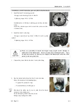
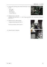
When using the J1 brake positioning jig (maintenance part):
Using the J1 brake positioning jig, check that the motor and the brake
core are aligned when fixing the brake.
If the J1 brake positioning jig cannot be inserted all the way, the motor
and the brake core may be misaligned. In such a case, use the brake
release unit (option part) to release the brake, and then align the brake.
Correct
Wrong
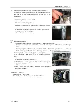
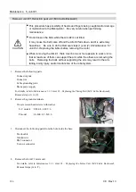
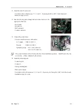
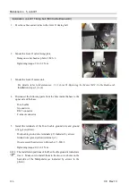
5.
Install the brake power supply to the plate. Make sure to install the
brake power supply so that the cables will be in the direction as
shown in the photo.
Cross recessed head screws with washer: 2-M3×6
Tightening torque: 0.45
±
0.1 N·m
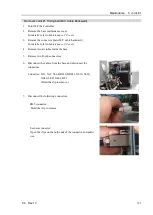
6.
Connect the following connectors.
Connectors: X11, X010, BT1, BR011
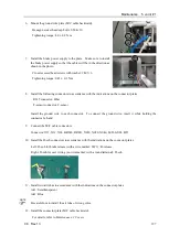
7.
Mount the connector plate (M/C cable backward).
For details, refer to
Maintenance: 3. Covers
.
8.
Mount the base maintenance cover.
For details, refer to
Maintenance: 3. Covers
.
9.
Calibrate the Joint #1.
For details, refer to
Maintenance: 16. Calibration
.
Summary of Contents for C8 Series
Page 1: ...Rev 13 EM208R4413F 6 Axis Robots C8 series MANIPULATOR MANUAL ...
Page 2: ...Manipulator manual C8 series Rev 13 ...
Page 8: ...vi C8 Rev 13 ...
Page 14: ...Table of Contents xii C8 Rev 13 ...
Page 16: ......
Page 31: ...Setup Operation 2 Specifications C8 Rev 13 17 2 4 Outer Dimensions Unit mm 2 4 1 C8 A701 C8 ...
Page 32: ...Setup Operation 2 Specifications 18 C8 Rev 13 2 4 2 C8 A901 C8L ...
Page 33: ...Setup Operation 2 Specifications C8 Rev 13 19 2 4 3 C8 A1401 C8XL ...
Page 49: ...Setup Operation 3 Environment and Installation C8 Rev 13 35 C8 A901 C8L ...
Page 98: ......
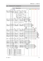
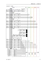
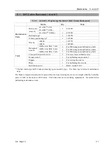
Page 183: ...Maintenance 4 Cable Unit C8 Rev 13 169 4 2 Connector Pin Assignment 4 2 1 Signal Cable ...
Page 184: ...Maintenance 4 Cable Unit 170 C8 Rev 13 ...
Page 185: ...Maintenance 4 Cable Unit C8 Rev 13 171 ...
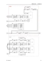
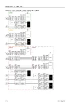
Page 186: ...Maintenance 4 Cable Unit 172 C8 Rev 13 4 2 2 Power Cable C8 A701 C8 C8 A901 C8L ...
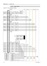
Page 187: ...Maintenance 4 Cable Unit C8 Rev 13 173 C8 A1401 C8XL ...
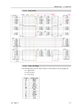
Page 188: ...Maintenance 4 Cable Unit 174 C8 Rev 13 C8 A701 C8 C8 A901 C8L C8 A1401 C8XL ...