


Setup & Operation 3. Environment and Installation
C8 Rev.13
41
Cleanroom-model Manipulator
For the Cleanroom-model, an exhaust system is necessary. For details, refer to
Setup &
Operation: 2.6 Specifications
.
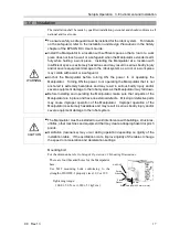
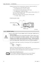
Protection-model Manipulator
For the Protection-model, also make sure to follow the following precautions.
CAUTION
■
When operating the Manipulator under special environmental conditions (adverse
conditions with dust and oily smoke), do not place the Controller in the same
condition since the Controller does not comply with IP67. Doing so may cause
equipment damage to and/or malfunction of the Controller.
■
After using the brake release unit, be sure to reconnect the external short
connector to the Manipulator. The brake release unit is not certified with the
protection rating (IP67).
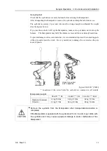
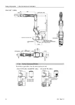
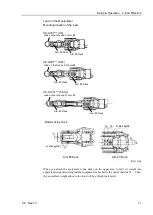
M/C Cable Connection method
Connect the power connector and the signal connector of the M/C cables to the Controller.
Grounding
WARNING
■
Ground resistance must be 100
Ω
or less. Improper ground resistance may
result in fire and/or electric shock.
■
Do not use the ground line for the Manipulator in common with other ground lines
or grounding electrodes for other electric power, motor power, welding devices,
etc. Using the ground line for the Manipulator in common with other ground lines
or grounding electrodes may result in electric shock and/or malfunction of the
robot system.
■
When using metal ducts, metallic conduits, or distributing racks for cable, ground
in accordance with national and local electric equipment technical standards.
Grounding that does not meet the standards may result in electric shock and/or
malfunction of the robot system.
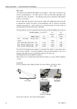
Follow local regulations for grounding. It is recommended that the core size of the
grounding wire be 5.5 mm
2
or more.
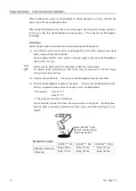
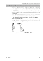
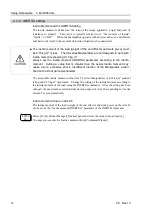
Directly connect the ground line to the Manipulator as shown in the figure below.
Detail of A
5.5 mm
2
or more
Bolt hole M5 (for grounding)
Summary of Contents for C8 Series
Page 1: ...Rev 13 EM208R4413F 6 Axis Robots C8 series MANIPULATOR MANUAL ...
Page 2: ...Manipulator manual C8 series Rev 13 ...
Page 8: ...vi C8 Rev 13 ...
Page 14: ...Table of Contents xii C8 Rev 13 ...
Page 16: ......
Page 31: ...Setup Operation 2 Specifications C8 Rev 13 17 2 4 Outer Dimensions Unit mm 2 4 1 C8 A701 C8 ...
Page 32: ...Setup Operation 2 Specifications 18 C8 Rev 13 2 4 2 C8 A901 C8L ...
Page 33: ...Setup Operation 2 Specifications C8 Rev 13 19 2 4 3 C8 A1401 C8XL ...
Page 49: ...Setup Operation 3 Environment and Installation C8 Rev 13 35 C8 A901 C8L ...
Page 98: ......
Page 183: ...Maintenance 4 Cable Unit C8 Rev 13 169 4 2 Connector Pin Assignment 4 2 1 Signal Cable ...
Page 184: ...Maintenance 4 Cable Unit 170 C8 Rev 13 ...
Page 185: ...Maintenance 4 Cable Unit C8 Rev 13 171 ...
Page 186: ...Maintenance 4 Cable Unit 172 C8 Rev 13 4 2 2 Power Cable C8 A701 C8 C8 A901 C8L ...
Page 187: ...Maintenance 4 Cable Unit C8 Rev 13 173 C8 A1401 C8XL ...
Page 188: ...Maintenance 4 Cable Unit 174 C8 Rev 13 C8 A701 C8 C8 A901 C8L C8 A1401 C8XL ...


