Setup & Operation 1. Safety
10
C8 Rev.13
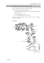
1.5.1 Moving the Arm using the brake release unit
The C8 series has the Brake Release Unit as an option.
For details, refer to
Setup & Option: 6 Options
.
1.5.2 Moving the Arm using the software
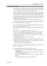
CAUTION
■
Normally, release the brake of joints one by one. Take extra care if you need to
release the brakes of two or more joints simultaneously. Releasing the brakes of
two or more joints simultaneously may cause hands and fingers to be caught
and/or equipment damage to or malfunction of the Manipulator as the arms of the
Manipulator may move in unexpected directions.
■
Be careful of the arm falling when releasing the brake.
While the brake is being released, the Manipulator’s arm falls by its own weight.
The arm falling may cause hands and fingers to be caught and/or may cause
equipment damage to or malfunction of the Manipulator.
■
Before releasing the brake, be sure to keep the Emergency Stop switch handy so
that you can immediately press the Emergency Stop switch. Otherwise, you
cannot immediately stop the arm falling due to an erroneous operation. The arm
falling may cause equipment damage to and/or malfunction of the Manipulator.
EPSON
RC+
After releasing the Emergency Stop switch, execute the following command in
[Command Window].
>Reset
>Brake Off,
[the number (from 1 to 6) corresponding to the arm whose brake will be
turned off]
Execute the following command to turn on the brake again.
>Brake On,
[The number (from 1 to 6) corresponding to the arm whose brake will be
turned on]
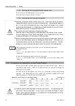
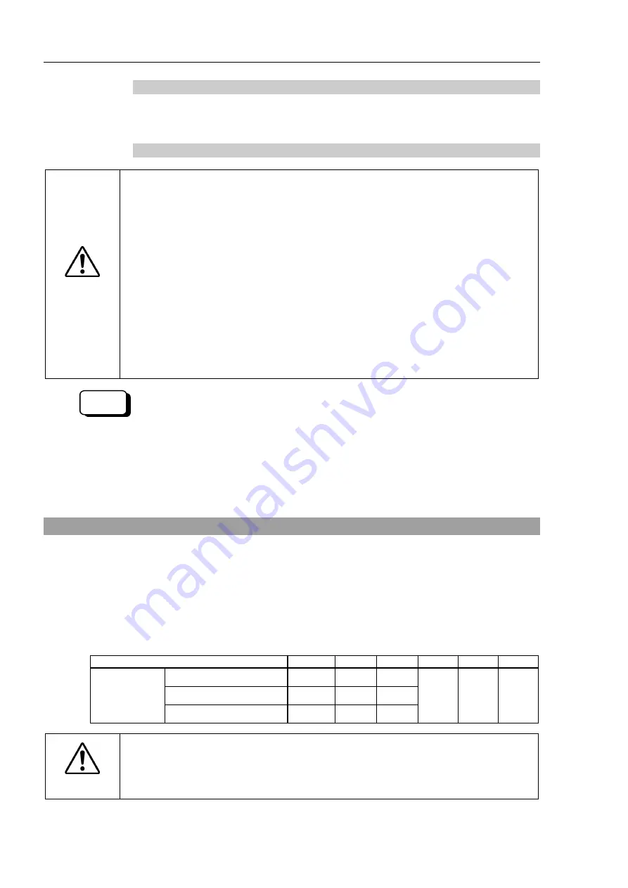
1.6 Precaution for Operation in Low Power Status
In the low power status, the Manipulator operates at low speed and low torque. However,
comparatively high torque as shown in the table below may be generated to support the
Manipulator’s own weight.
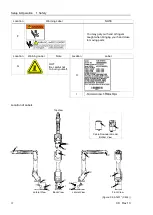
Carefully operate the Manipulator since it may get your hands or fingers caught during
operation. The Manipulator may also collide with peripheral equipment and cause
equipment damage to or malfunction of the Manipulator.
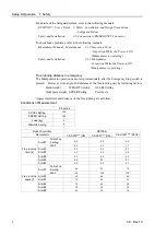
Maximum Joint Torque in Low Power Status
[Unit: N·m]
Joint
#1
#2
#3
#4
#5
#6
Joint Torque
C8-A701***
(C8)
144.9
245.1
114.2
35.0
40.0
20.5
C8-A901***
(C8L)
149.5
270.9
129.3
C8-A1401*** (C8XL)
299.9
487.6
248.9
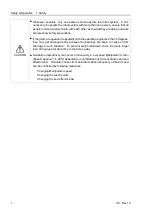
CAUTION
■
Carefully operate the Manipulator in the low power status. A comparatively high
joint torque may be generated. It may cause your hands and fingers caught
and/or cause equipment damage to or malfunction of the Manipulator as it may
collide with peripheral equipment.
Summary of Contents for C8 Series
Page 1: ...Rev 13 EM208R4413F 6 Axis Robots C8 series MANIPULATOR MANUAL ...
Page 2: ...Manipulator manual C8 series Rev 13 ...
Page 8: ...vi C8 Rev 13 ...
Page 14: ...Table of Contents xii C8 Rev 13 ...
Page 16: ......
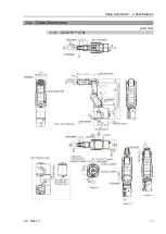
Page 31: ...Setup Operation 2 Specifications C8 Rev 13 17 2 4 Outer Dimensions Unit mm 2 4 1 C8 A701 C8 ...
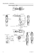
Page 32: ...Setup Operation 2 Specifications 18 C8 Rev 13 2 4 2 C8 A901 C8L ...
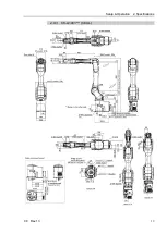
Page 33: ...Setup Operation 2 Specifications C8 Rev 13 19 2 4 3 C8 A1401 C8XL ...
Page 49: ...Setup Operation 3 Environment and Installation C8 Rev 13 35 C8 A901 C8L ...
Page 98: ......
Page 183: ...Maintenance 4 Cable Unit C8 Rev 13 169 4 2 Connector Pin Assignment 4 2 1 Signal Cable ...
Page 184: ...Maintenance 4 Cable Unit 170 C8 Rev 13 ...
Page 185: ...Maintenance 4 Cable Unit C8 Rev 13 171 ...
Page 186: ...Maintenance 4 Cable Unit 172 C8 Rev 13 4 2 2 Power Cable C8 A701 C8 C8 A901 C8L ...
Page 187: ...Maintenance 4 Cable Unit C8 Rev 13 173 C8 A1401 C8XL ...
Page 188: ...Maintenance 4 Cable Unit 174 C8 Rev 13 C8 A701 C8 C8 A901 C8L C8 A1401 C8XL ...

