


Maintenance 7. Joint #3
C8 Rev.13
243
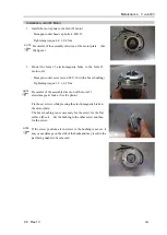
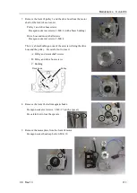
6.
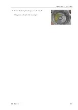
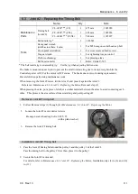
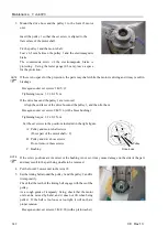
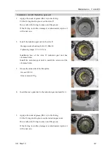
Apply tension to the Joint #3 timing belt and fix the Joint #3
motor unit.
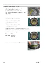
Joint #3 timing belt tension: 25 to 85 N
Belt tension meter setting value
Weight: 2.5 g/mm width × m span, Width: 10 mm,
Span: 168 mm
Hexagon socket set screw: 3-M4×20 (with a plain washer)
Tightening torque: 4.0
±
0.2 N
·
m
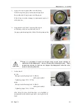
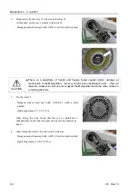
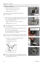
Regarding belt tension:
-
Jumping (position gap) may occur if the value is below the lower limit
-
Vibration (abnormal noise) or reduction of life of the parts may occur if the value exceeds the upper
limit.
-
When you replace with a new belt, belt extends and the belt tension may decrease in the initial stage.
Make sure to operate the robot two to three days and check the belt tension again.
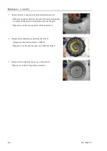
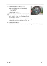
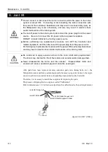
When using the belt tension tensile jig (maintenance part):
Fix the belt tension tensile jig (for J1, J2, J3) with the screws (2-M4×35) and push the rubber against the
pulley.
Tension is applied by pushing the set screw (M6
×
25) with the rubber.
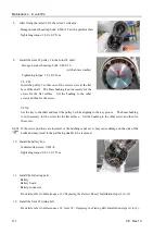
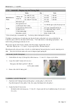
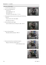
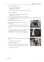
7.
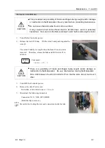
Install the brake power supply.
Cross recessed head screw with captive washer: 2-M3×6
Tightening torque: 0.45
±
0.1 N·m
8.
Connect the following connectors.
Connectors: X131, X031, BT3, BR031
9.
Install the Arm #2 side cover.
For details, refer to
Maintenance: 3. Covers.
10.
Perform the calibration.
For details, refer to
Maintenance: 16. Calibration.
NOTE
Summary of Contents for C8 Series
Page 1: ...Rev 13 EM208R4413F 6 Axis Robots C8 series MANIPULATOR MANUAL ...
Page 2: ...Manipulator manual C8 series Rev 13 ...
Page 8: ...vi C8 Rev 13 ...
Page 14: ...Table of Contents xii C8 Rev 13 ...
Page 16: ......
Page 31: ...Setup Operation 2 Specifications C8 Rev 13 17 2 4 Outer Dimensions Unit mm 2 4 1 C8 A701 C8 ...
Page 32: ...Setup Operation 2 Specifications 18 C8 Rev 13 2 4 2 C8 A901 C8L ...
Page 33: ...Setup Operation 2 Specifications C8 Rev 13 19 2 4 3 C8 A1401 C8XL ...
Page 49: ...Setup Operation 3 Environment and Installation C8 Rev 13 35 C8 A901 C8L ...
Page 98: ......
Page 183: ...Maintenance 4 Cable Unit C8 Rev 13 169 4 2 Connector Pin Assignment 4 2 1 Signal Cable ...
Page 184: ...Maintenance 4 Cable Unit 170 C8 Rev 13 ...
Page 185: ...Maintenance 4 Cable Unit C8 Rev 13 171 ...
Page 186: ...Maintenance 4 Cable Unit 172 C8 Rev 13 4 2 2 Power Cable C8 A701 C8 C8 A901 C8L ...
Page 187: ...Maintenance 4 Cable Unit C8 Rev 13 173 C8 A1401 C8XL ...
Page 188: ...Maintenance 4 Cable Unit 174 C8 Rev 13 C8 A701 C8 C8 A901 C8L C8 A1401 C8XL ...


