Maintenance 8. Joint #4
C8 Rev.13
269
Installation: Joint #4 Timing belt
1.
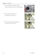
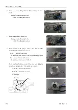
Pass the Joint #4 timing belt around the Joint #4 pulley 2
2.
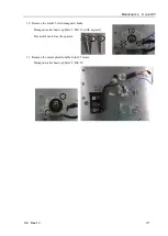
Install the Joint #4 motor unit.
For details, refer to
Maintenance: 8.1 Joint #4 – Replacing the Motor
, Installation steps (4) through (6).
3.
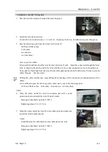
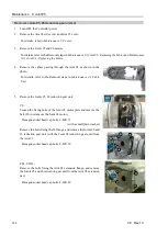
Pass the following parts from the Arm #3 to the Arm #4.
X052 and X062 cables
LAN cable
Ground wire
Air tube (blue)
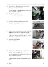
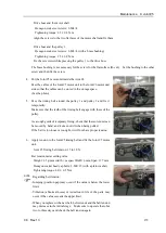
How to pass the cables:
First pass the braid tube from the Arm #4 side to the Arm #3 side. Insert the connectors through the braid
tube, as shown in the photo, and fix the tube with the wire tie so that connectors are not to be pulled out.
Then, pull the braid tube from the Arm #4 side while pushing the cables from the Arm #3 side to pass the
cables through. (See the photo.)
Pulling the cables forcibly may cause falling off or breakage of the connectors and disconnection of the
cables.
If it is difficult to pass the cables, pass the cables one by one in the following order.
X052 and X062 cables LAN cable Ground wire Air tube (blue)
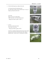
C8XL:
4.
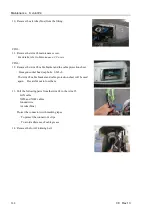
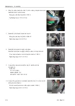
Wrap the cables inside the Arm #4 extension part with a cable
protection sheet and install the Arm #4 cable bracket.
Hexagon socket head cap bolts: 2-M3
×
6
Tightening torque: 2.0
±
0.1 N·m
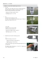
5.
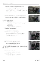
Wrap the cables inside the Arm #4 with a cable protection sheet and
install the Arm #4 cable bracket.
C8XL:
Install the Arm #4 cable bracket on the cable protection tube.
Hexagon socket head cap bolts: 2-M3
×
6
Tightening torque: 2.0
±
0.1 N·m
NOTE
Summary of Contents for C8 Series
Page 1: ...Rev 13 EM208R4413F 6 Axis Robots C8 series MANIPULATOR MANUAL ...
Page 2: ...Manipulator manual C8 series Rev 13 ...
Page 8: ...vi C8 Rev 13 ...
Page 14: ...Table of Contents xii C8 Rev 13 ...
Page 16: ......
Page 31: ...Setup Operation 2 Specifications C8 Rev 13 17 2 4 Outer Dimensions Unit mm 2 4 1 C8 A701 C8 ...
Page 32: ...Setup Operation 2 Specifications 18 C8 Rev 13 2 4 2 C8 A901 C8L ...
Page 33: ...Setup Operation 2 Specifications C8 Rev 13 19 2 4 3 C8 A1401 C8XL ...
Page 49: ...Setup Operation 3 Environment and Installation C8 Rev 13 35 C8 A901 C8L ...
Page 98: ......
Page 183: ...Maintenance 4 Cable Unit C8 Rev 13 169 4 2 Connector Pin Assignment 4 2 1 Signal Cable ...
Page 184: ...Maintenance 4 Cable Unit 170 C8 Rev 13 ...
Page 185: ...Maintenance 4 Cable Unit C8 Rev 13 171 ...
Page 186: ...Maintenance 4 Cable Unit 172 C8 Rev 13 4 2 2 Power Cable C8 A701 C8 C8 A901 C8L ...
Page 187: ...Maintenance 4 Cable Unit C8 Rev 13 173 C8 A1401 C8XL ...
Page 188: ...Maintenance 4 Cable Unit 174 C8 Rev 13 C8 A701 C8 C8 A901 C8L C8 A1401 C8XL ...

