


Maintenance 5. Joint #1
186
C8 Rev.13
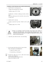
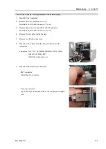
Removal: Joint #1 Reduction gear unit (M/C Cable Backward)
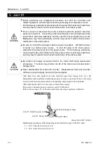
CAUTION
■
This procedure has possibility of hands and fingers being caught and/or damage
or malfunction to the Manipulator. Be very careful when performing
maintenance.
■
Do not loosen the bolts while the Arm #2 is not tilted.
It may cause the belt come off and the Arm #2 falls down, and it is extremely
hazardous. Be sure to do the Removal steps (1) and (2) in
Maintenance 6.1
Joint #2 - Replacing the Motor
before removing the motor.
■
When removing the Arm #1, there must be two or more people to work on it so
that at least one of them can support the arm while the others are removing the
bolts. Removing the bolts without supporting the arm may result in the arm
falling, bodily injury, and/or malfunction of the robot system.
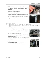
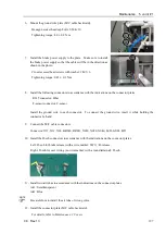
1.
Remove the following parts.
Connector plate
Connector
Cable grounding plate
Brake power supply
For details, refer to
Maintenance 5.1.3 Joint #1 - Replacing the Timing Belt (M/C Cable Backward)
,
Removal steps (1) to (9).
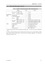
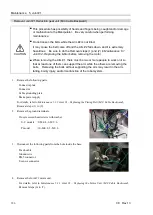
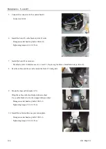
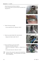
2.
Remove the ground terminals.
Cross recessed head screws with washer
S, C models : 9-M4×8, 2-M3×6
P model
: 10-M4×8, 2-M3×6
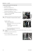
3.
Disconnect the following parts from the hole inside the base.
D-sub cable
Ground wire
RJ45 connector
F-sensor connector
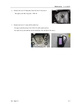
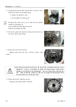
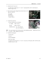
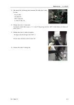
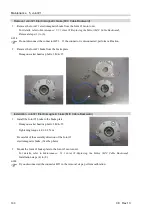
4.
Remove the Joint #1 motor unit.
For details, refer to
Maintenance 5.1.1 Joint #1 – Replacing the Motor Unit (M/C Cable Backward)
,
Removal steps (6) to (7).
Summary of Contents for C8 Series
Page 1: ...Rev 13 EM208R4413F 6 Axis Robots C8 series MANIPULATOR MANUAL ...
Page 2: ...Manipulator manual C8 series Rev 13 ...
Page 8: ...vi C8 Rev 13 ...
Page 14: ...Table of Contents xii C8 Rev 13 ...
Page 16: ......
Page 31: ...Setup Operation 2 Specifications C8 Rev 13 17 2 4 Outer Dimensions Unit mm 2 4 1 C8 A701 C8 ...
Page 32: ...Setup Operation 2 Specifications 18 C8 Rev 13 2 4 2 C8 A901 C8L ...
Page 33: ...Setup Operation 2 Specifications C8 Rev 13 19 2 4 3 C8 A1401 C8XL ...
Page 49: ...Setup Operation 3 Environment and Installation C8 Rev 13 35 C8 A901 C8L ...
Page 98: ......
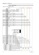
Page 183: ...Maintenance 4 Cable Unit C8 Rev 13 169 4 2 Connector Pin Assignment 4 2 1 Signal Cable ...
Page 184: ...Maintenance 4 Cable Unit 170 C8 Rev 13 ...
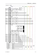
Page 185: ...Maintenance 4 Cable Unit C8 Rev 13 171 ...
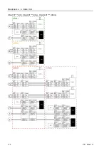
Page 186: ...Maintenance 4 Cable Unit 172 C8 Rev 13 4 2 2 Power Cable C8 A701 C8 C8 A901 C8L ...
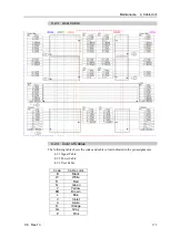
Page 187: ...Maintenance 4 Cable Unit C8 Rev 13 173 C8 A1401 C8XL ...
Page 188: ...Maintenance 4 Cable Unit 174 C8 Rev 13 C8 A701 C8 C8 A901 C8L C8 A1401 C8XL ...