


Maintenance 5. Joint #1
C8 Rev.13
193
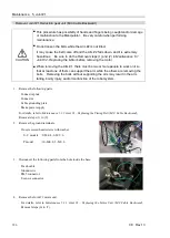
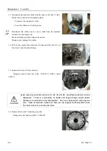
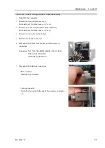
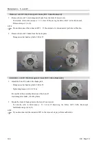
Removal: Joint #1 Timing belt (M/C Cable Backward)
1.
Turn OFF the Controller.
2.
Remove the base maintenance cover.
For details, refer to
Maintenance 3. Covers
.
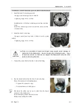
3.
Remove the connector plate (M/C cable backward).
For details, refer to
Maintenance 3. Covers
.
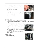
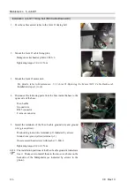
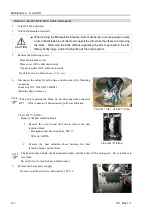
4.
Remove two air tubes inside the base.
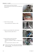
5.
Remove two D-sub connectors.
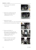
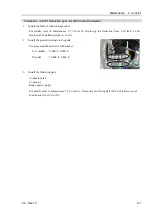
6.
Disconnect the cables from the base and disconnect the
connectors.
Connector: X11, X12, X14, BR010, BR011, X010, X020,
X040, LED, GS01, BT1
(Hold the clip to remove.)
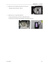
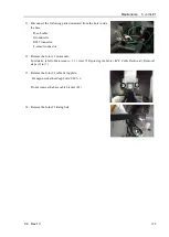
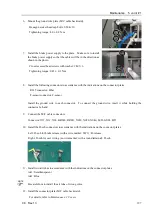
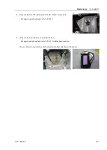
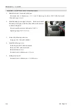
7.
Disconnect the following connectors.
RJ45 connector:
Hold the clip to remove.
F-sensor connector:
Open the clips on the both ends of the connector and pull it
out.
Summary of Contents for C8 Series
Page 1: ...Rev 13 EM208R4413F 6 Axis Robots C8 series MANIPULATOR MANUAL ...
Page 2: ...Manipulator manual C8 series Rev 13 ...
Page 8: ...vi C8 Rev 13 ...
Page 14: ...Table of Contents xii C8 Rev 13 ...
Page 16: ......
Page 31: ...Setup Operation 2 Specifications C8 Rev 13 17 2 4 Outer Dimensions Unit mm 2 4 1 C8 A701 C8 ...
Page 32: ...Setup Operation 2 Specifications 18 C8 Rev 13 2 4 2 C8 A901 C8L ...
Page 33: ...Setup Operation 2 Specifications C8 Rev 13 19 2 4 3 C8 A1401 C8XL ...
Page 49: ...Setup Operation 3 Environment and Installation C8 Rev 13 35 C8 A901 C8L ...
Page 98: ......
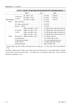
Page 183: ...Maintenance 4 Cable Unit C8 Rev 13 169 4 2 Connector Pin Assignment 4 2 1 Signal Cable ...
Page 184: ...Maintenance 4 Cable Unit 170 C8 Rev 13 ...
Page 185: ...Maintenance 4 Cable Unit C8 Rev 13 171 ...
Page 186: ...Maintenance 4 Cable Unit 172 C8 Rev 13 4 2 2 Power Cable C8 A701 C8 C8 A901 C8L ...
Page 187: ...Maintenance 4 Cable Unit C8 Rev 13 173 C8 A1401 C8XL ...
Page 188: ...Maintenance 4 Cable Unit 174 C8 Rev 13 C8 A701 C8 C8 A901 C8L C8 A1401 C8XL ...