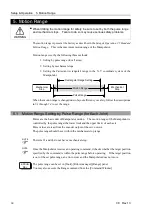


Setup & Operation 5. Motion Range
C8 Rev.13
73
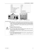
(6)
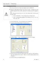
Select the series name of the Manipulator in the [Series] box.
(7)
Select the robot model in the [Model] box. Available robots will be displayed
according to the format of the currently installed motor driver. When [Dry run] is used,
all the Manipulators of the series selected in Step 6 will be displayed.
(8)
Click the <OK> button. The Controller will be restarted.
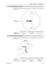
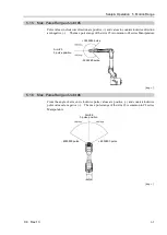
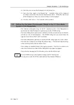
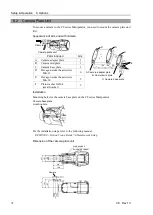
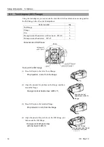
5.6 Setting the Cartesian (Rectangular) Range in the XY Coordinate
System of the Manipulator
The Cartesian (rectangular) range in the XY coordinate system of the Manipulator is
specified by the limited Manipulator operation area and the XYLIM setting.
The limited Manipulator operation area is defined so that the end effector does not interfere
with the rear side of the Manipulator. The XYLIM setting that you can determines the
upper and lower limits of the X and Y coordinates.
The limited Manipulator operation area and the XYLIM setting apply only to the software.
Therefore, these settings do not change the physical range. The maximum physical range
is based on the position of the mechanical stops.
These settings are disabled during a joint jogging operation. Therefore, be careful not to
allow the end effector to collide with the Manipulator or peripheral equipment.
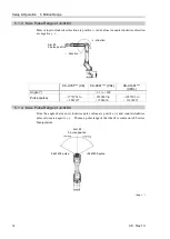
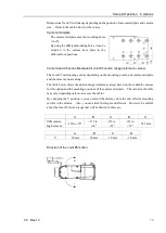
The method for changing the XYLIM setting varies with the software used.
EPSON
RC+
Set the XYLIM setting in [Tools]-[Robot manager]-[XYZ Limits] panel.
You may also execute the XYLim command from the [Command Window].
Summary of Contents for C8 Series
Page 1: ...Rev 13 EM208R4413F 6 Axis Robots C8 series MANIPULATOR MANUAL ...
Page 2: ...Manipulator manual C8 series Rev 13 ...
Page 8: ...vi C8 Rev 13 ...
Page 14: ...Table of Contents xii C8 Rev 13 ...
Page 16: ......
Page 31: ...Setup Operation 2 Specifications C8 Rev 13 17 2 4 Outer Dimensions Unit mm 2 4 1 C8 A701 C8 ...
Page 32: ...Setup Operation 2 Specifications 18 C8 Rev 13 2 4 2 C8 A901 C8L ...
Page 33: ...Setup Operation 2 Specifications C8 Rev 13 19 2 4 3 C8 A1401 C8XL ...
Page 49: ...Setup Operation 3 Environment and Installation C8 Rev 13 35 C8 A901 C8L ...
Page 98: ......
Page 183: ...Maintenance 4 Cable Unit C8 Rev 13 169 4 2 Connector Pin Assignment 4 2 1 Signal Cable ...
Page 184: ...Maintenance 4 Cable Unit 170 C8 Rev 13 ...
Page 185: ...Maintenance 4 Cable Unit C8 Rev 13 171 ...
Page 186: ...Maintenance 4 Cable Unit 172 C8 Rev 13 4 2 2 Power Cable C8 A701 C8 C8 A901 C8L ...
Page 187: ...Maintenance 4 Cable Unit C8 Rev 13 173 C8 A1401 C8XL ...
Page 188: ...Maintenance 4 Cable Unit 174 C8 Rev 13 C8 A701 C8 C8 A901 C8L C8 A1401 C8XL ...